|
BRHS /
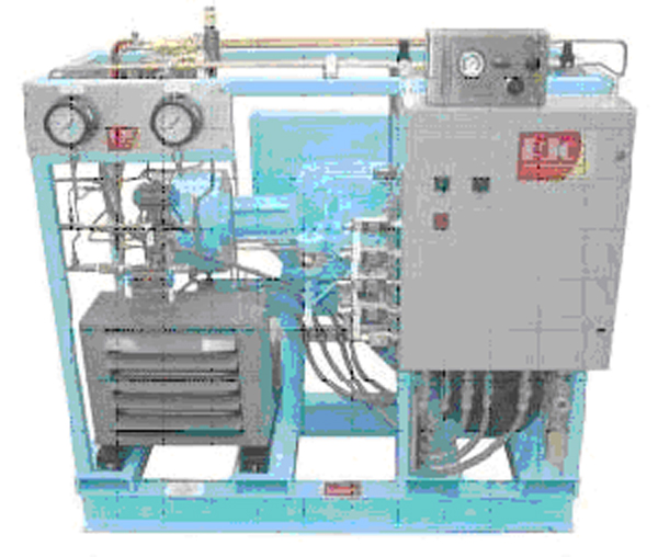
CompressorsCompressors Raising the hydrogen gas pressure for its storage (150 bar to 300 bar in industrial applications, currently up to 700 for vehicle applications) or transportation in pipelines (typically 100 bars) is achieved with volumetric compressors. Either piston or diaphragm compressors are used. The latter type is often preferred because it fully preserves the products purity and requires little maintenance. Two examples of hydrogen compressors are shown in figure 1 and 2. Multi-stage piston compressors are more effective when the ratio between outlet and inlet pressure is large. This is typically the case when the inlet pressure is very low (a few bars or less). If the piston is oil lubricated, an oil removal system is necessary. For small and intermittent hydrogen flows such as those encountered at the end of a vehicle tank refuelling cycle (when pressure is maximum), compressed air driven reciprocating compressor are sometimes chosen for reasons of simplicity and compactness. In fuelling station applications, a combination of compression technologies may be used to perform the various compression steps necessary, taking into account operating time and duty cycle in order to minimize total ownership costs. Thermal compression Compressing hydrogen to 700 bar by the means presented above requires application of mechanical energy representing approximately 10% of the gas’ energy content. Thermal hydride hydrogen compression is a means to compress hydrogen by applying only heat. In the thermal compressor, hydrogen is absorbed in a reversible metal hydride alloy at low pressure in a water-cooled container. The container is subsequently heated with hot water, which releases the hydrogen at higher pressure. Continuous compression is achieved with two identical containers in a parallel configuration; one container is cooled by water and absorbs hydrogen until it is full, while the other container is heated with hot water in order to release hydrogen at the same rate. The cool and hot water streams are periodically switched and simple check valves keep hydrogen moving through the thermal compressor. By employing successively higher pressure hydride alloy stages in series, high pressure ratios can be generated. Hydride compressors are compact and silent. When powered by waste heat, energy consumption cost is only a fraction of that required for mechanical compression. However, thermal compression of hydrogen using metal hydrides requires pure hydrogen streams that typically have less than 50 ppm of active gas impurities, as impurities can react with the hydride alloy and reduce its hydrogen storage capacity and/or impede the absorption of hydrogen. Flow rate is limited by heat transfer limitations associated with large alloy beds. Indeed, when metal hydride alloys absorb hydrogen, the chemical reaction is exothermic and heat is generated. This heat must be removed from the alloy in order to continue the absorption process to completion. Likewise, the alloy must be heated to release hydrogen. The rate of hydrogen throughput depends upon the speed that heat can be transferred into or away from the alloy. Improving heat transfer rate increases hydrogen throughput. Hydride compressors built to date have flow rates not exceeding a few tens of Nm3/h. Design safety considerations specific to hydrogen service in addition to those generally considered for gas compressing systems are indicated below : Materials The compressor must be designed with particular reference to hydrogen service. In particular all metallic material wetted by pressurized hydrogen must be suitable for hydrogen, i.e. not susceptible to hydrogen embrittlement unless used at low enough stress or without consequence on safety in case of failure. Prevention of ingress of air at inlet To avoid a vacuum in the inlet line and consequent ingress of air in the event hydrogen feed is closed off , the inlet pressure needs to be monitored with automatic compressor shut-down before this pressure drops below ambient pressure. Monitoring of oxygen content at inlet Where the hydrogen comes from a low-pressure source, or where there is a possibility of oxygen contamination, the oxygen content needs to be monitored with automatic compressor shut-down if the oxygen content exceeds 1%. Discharge temperature control As they may put at risk vital functions of process equipment, situations of excessive compressor discharge temperature, must be detected with immediate corrective actions such as compressor shut-down. Prevention of hydrogen-air mixtures in internal volumes Absence of air in internal volumes to which hydrogen may leak, such as the crank-case, needs to be ensured, for instance by pressurisation (with hydrogen or nitrogen). Over-pressure relief from internal hydrogen leaks The vents of pressure relief devices protecting secondary circuits such as a closed water cooling circuit or the crank case against overpressure arising from a leak from the hydrogen side need to be arranged so that their discharge will not generate a dangerous situation. Regarding compressed H2 purity, contamination risks originating from the compressor need to be considered. With oil lubricated piston compressors, oil contamination can result from malfunction of the oil removal system. With diaphragm compressors there is the potential of product contamination by hydraulic oil in case of diaphragm failure. This is typically prevented by using double or multi-layer diaphragm constructions with a leak detection system. The compressor’s cooling water circuit is another potential source of contamination which needs to be considered closely especially for vehicle fuelling application, considering that such water contamination may have adverse effects on the vehicle’s on-board storage if its liner is made of a material sensitive to stress corrosion. This is often the case for the grades of aluminium typically used in such applications. References HOFER (2006) Dry-running HOFER piston compressors for hydrogen application with hydraulic drive unit, type TKH..(BibTeX) |