|
BRHS /
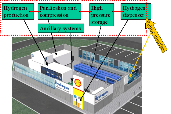
Gaseous Hydrogen Refuelling StationsGeneral Several demonstration projects involving hydrogen refuelling stations are in operation. Examples from Europe are the CUTE and HyFleet:CUTE projects, ECTOS project and the CEP Berlin project. In the large European demonstration project, CUTE, 30 hydrogen operated fuel cell buses have been test-driven in 9 European cities. Hydrogen refueling stations have also been located in these 9 cities. The following descriptions and technology examples from hydrogen refuelling stations are mainly based on such demonstration projects as the CUTE, ECTOS and the CEP Berlin project. Today's hydrogen gaseous stations are usually based on a few main components: Hydrogen on site production or supply by pipeline or truck delivery
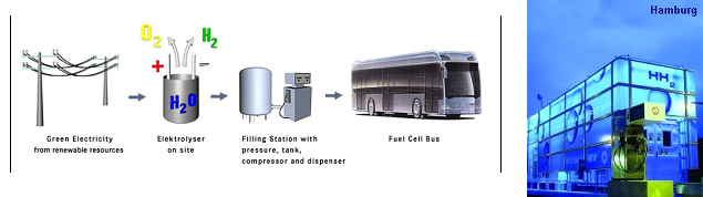
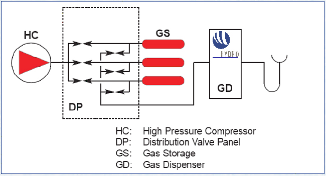
A 3D drawing illustrating the main system components at the refuelling station at Iceland in the ECTOS project is illustrated in figure 1. Below 2 hydrogen refuelling stations from the CUTE project are described. CUTE station in Hamburg The concept in Hamburg is illustrated below in figure 2. At the Hamburg station hydrogen is produced on-site by electrolysis using electricity The filling station and production facilities are located at HOCHBAHN's bus depot in Hamburg Hummelsbüttel. Using electricity from the grid and combining this with the production from certified green electricity for the hydrogen production on-site is fulfilling all goals of ecology and sustainability. A pressurised electrolyser (15 bar) produces high purity hydrogen with high efficiency which is then compressed to 450 bar and stored in on-site storage tanks. Busses can be filled up with 40 kg of hydrogen in 10 minutes which enables them to operate up to a range of 250 -300 km. CUTE station in Madrid At the station in Madrid there are two options for hydrogen supply: on-site production by natural gas reforming and gaseous hydrogen.delivered by truck. The concept is illustrated in figure 3. Hydrogen is delivered by 200 bar by tube trailers. Each one of them contains 3960 Nm3, composed of 264 small cylinders (85 liters) with hydrogen compatible with fuel cell requirements. Gas compression from these tube trailers to the bus is done by a water cooled membrane compressor. In Madrid Hydrogen is also produced on-site by a natural gas steam reforming process. An example of a principal sketch of a refuelling station concept downstream the production or supply unit is shown in figure 4. Compression The produced hydrogen, after being dried and purified, is compressed to about 450 bar (typical for the CUTE stations). The compressor(s) are usually located within an enclosure. Buffer storage Hydrogen is accumulated in high-pressure buffer vessels for fast transfer by pressure difference to the vehicle tank.. In order to minimize compression energy, the buffer is made up of multiple storage banks at different pressures, with the gas being taken first from the lower pressure bank (this pressure being sufficient to transfer product to the vehicle storage at initially low pressure) and then successively from pressure banks of increasing pressure. This is referred to as cascade refuelling further described hereafter. Maximum buffer storage pressure of 440 bar is typically required to refuell vehicles with 350 bar storage, in order to account for the temperature increase in the vehicle storage due to the fast filling. 700 bar refuelling requires 880 bar buffer storage. Dispenser/refuelling The description below for the refuelling system is based on cascade filling and high pressure storage. There may also be other alternatives. The Fuel Gas Dispenser is usually a "stand-alone" unit, which provides the mechanical interface between the hydrogen fuel station storage tanks and the vehicle, together with safety features and metering equipment. The dispenser consists of a small enclosure where regulation and control valves are located. The principle of cascade filling can be explained for a 3 cascades concept as follows: The vehicles will start to fill from the low pressure bank. When the pressure in storage tank and vehicle tank is balanced, the filling will automatically continue from the next cascade, medium pressure bank. Finally, the filling will be completed by topping up the vehicle tanks from the high pressure bank. This process is usually fully automatic. A two stage cascade filling system combined with a booster compressor, or a multiple stage cascade filling system with more than three pressure banks are other options. This is to ensure that the on-board vehicle storage tank reaches the appropriate fill pressure within the required time. The compressed gas hydrogen dispenser usually has a vent stack line to the atmosphere. Purging system Inert gas purging systems, which can be initiated automatically or manually are important ancillary parts of the filling station. Inert gas purging systems may be used during start up and shutdown and in emergency situations. Manning Future hydrogen filling stations, including the Hydrogen production unit, may be fully automated and can be unattended, with remote supervision.. In case of deviations from normal operation conditions, the system is designed so that it will shut down to safe conditions automatically. Shutdown can also be initiated by pressing emergency buttons at the filling station area or from a remote location. In the CUTE project , the stations were designed for refuelling of 3 buses per day, which corresponds to a production capacity of 60 Nm3/h. Most stations in demonstration projects are only able to refuel a few vehicles (buses or cars) per day, and there is still a long way to go to achieve the same capacity as for petrol and gasoline stations. The reasons are challenges related to storage capacity (available area and volume), safety (high pressures) and the requirement for short refuelling durations. For overnight refuelling the technical requirements are less challenging. Most existing hydrogen refuelling stations are part of demonstration projects, and, so far, all require that the users receive proper education and training with regard to the safety related properties of hydrogen and the vehicle refuelling process. The refuelling technology is new and not fully mature, very high storage pressures are necessary to obtain the desired autonomy, and gaseous fuels still are quite uncommon in most countries. However, experience from the demonstration projects will allow improve the technology, as well as the public’s “familiarity” with new types of fuels. << Transport in compound materials | Content | Liquid Hydrogen refuelling stations >> |