|
BRHS /
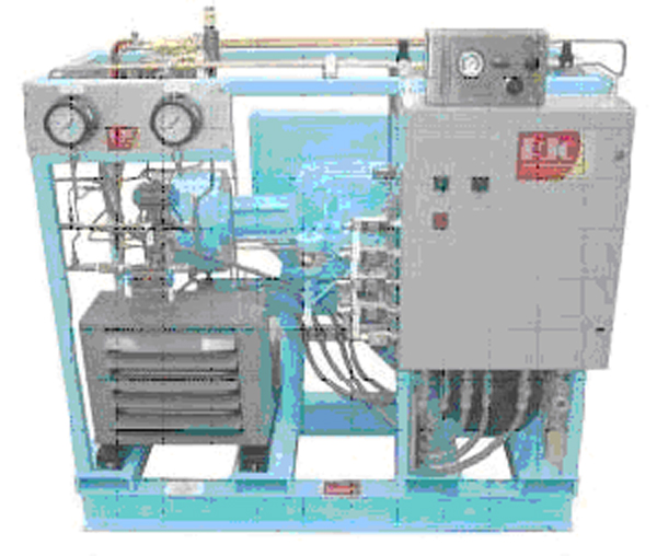
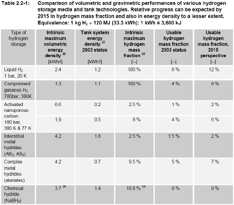
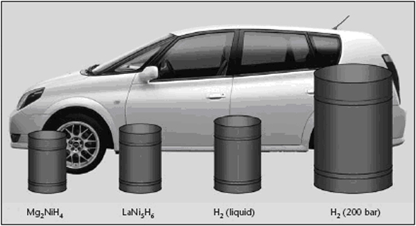
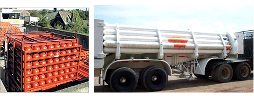
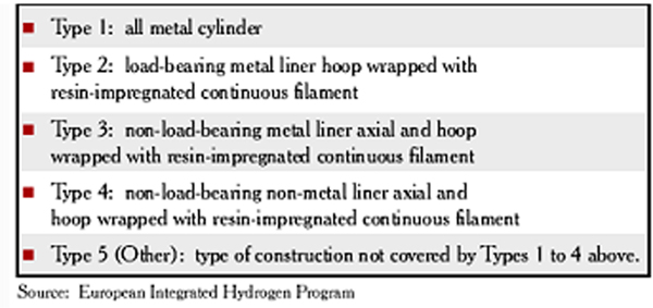
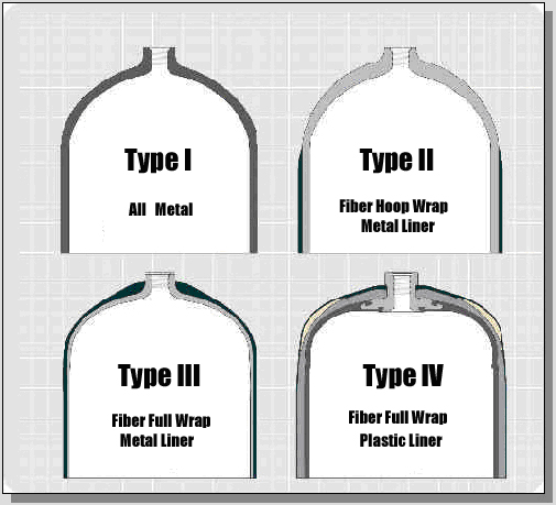
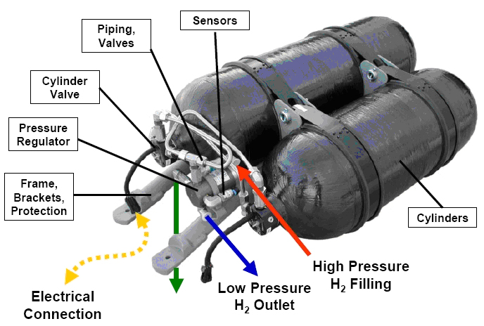
OFD-Chapter2-H2-System-Main-ComponentsHydrogen Systems Main ComponentsOnce hydrogen has been produced, several steps are usually necessary to transport and/or liquefy/compress the gas before it can be sent to the end-user for storage or use. Below a short description of main components, which are often needed in this process. CompressorsCompressors Raising the hydrogen gas pressure for its storage (150 bar to 300 bar in industrial applications, currently up to 700 for vehicle applications) or transportation in pipelines (typically 100 bars) is achieved with volumetric compressors. Either piston or diaphragm compressors are used. The latter type is often preferred because it fully preserves the products purity and requires little maintenance. Two examples of hydrogen compressors are shown in figure 1 and 2. Multi-stage piston compressors are more effective when the ratio between outlet and inlet pressure is large. This is typically the case when the inlet pressure is very low (a few bars or less). If the piston is oil lubricated, an oil removal system is necessary. For small and intermittent hydrogen flows such as those encountered at the end of a vehicle tank refuelling cycle (when pressure is maximum), compressed air driven reciprocating compressor are sometimes chosen for reasons of simplicity and compactness. In fuelling station applications, a combination of compression technologies may be used to perform the various compression steps necessary, taking into account operating time and duty cycle in order to minimize total ownership costs. Thermal compression Compressing hydrogen to 700 bar by the means presented above requires application of mechanical energy representing approximately 10% of the gas’ energy content. Thermal hydride hydrogen compression is a means to compress hydrogen by applying only heat. In the thermal compressor, hydrogen is absorbed in a reversible metal hydride alloy at low pressure in a water-cooled container. The container is subsequently heated with hot water, which releases the hydrogen at higher pressure. Continuous compression is achieved with two identical containers in a parallel configuration; one container is cooled by water and absorbs hydrogen until it is full, while the other container is heated with hot water in order to release hydrogen at the same rate. The cool and hot water streams are periodically switched and simple check valves keep hydrogen moving through the thermal compressor. By employing successively higher pressure hydride alloy stages in series, high pressure ratios can be generated. Hydride compressors are compact and silent. When powered by waste heat, energy consumption cost is only a fraction of that required for mechanical compression. However, thermal compression of hydrogen using metal hydrides requires pure hydrogen streams that typically have less than 50 ppm of active gas impurities, as impurities can react with the hydride alloy and reduce its hydrogen storage capacity and/or impede the absorption of hydrogen. Flow rate is limited by heat transfer limitations associated with large alloy beds. Indeed, when metal hydride alloys absorb hydrogen, the chemical reaction is exothermic and heat is generated. This heat must be removed from the alloy in order to continue the absorption process to completion. Likewise, the alloy must be heated to release hydrogen. The rate of hydrogen throughput depends upon the speed that heat can be transferred into or away from the alloy. Improving heat transfer rate increases hydrogen throughput. Hydride compressors built to date have flow rates not exceeding a few tens of Nm3/h. Design safety considerations specific to hydrogen service in addition to those generally considered for gas compressing systems are indicated below : Materials The compressor must be designed with particular reference to hydrogen service. In particular all metallic material wetted by pressurized hydrogen must be suitable for hydrogen, i.e. not susceptible to hydrogen embrittlement unless used at low enough stress or without consequence on safety in case of failure. Prevention of ingress of air at inlet To avoid a vacuum in the inlet line and consequent ingress of air in the event hydrogen feed is closed off , the inlet pressure needs to be monitored with automatic compressor shut-down before this pressure drops below ambient pressure. Monitoring of oxygen content at inlet Where the hydrogen comes from a low-pressure source, or where there is a possibility of oxygen contamination, the oxygen content needs to be monitored with automatic compressor shut-down if the oxygen content exceeds 1%. Discharge temperature control As they may put at risk vital functions of process equipment, situations of excessive compressor discharge temperature, must be detected with immediate corrective actions such as compressor shut-down. Prevention of hydrogen-air mixtures in internal volumes Absence of air in internal volumes to which hydrogen may leak, such as the crank-case, needs to be ensured, for instance by pressurisation (with hydrogen or nitrogen). Over-pressure relief from internal hydrogen leaks The vents of pressure relief devices protecting secondary circuits such as a closed water cooling circuit or the crank case against overpressure arising from a leak from the hydrogen side need to be arranged so that their discharge will not generate a dangerous situation. Regarding compressed H2 purity, contamination risks originating from the compressor need to be considered. With oil lubricated piston compressors, oil contamination can result from malfunction of the oil removal system. With diaphragm compressors there is the potential of product contamination by hydraulic oil in case of diaphragm failure. This is typically prevented by using double or multi-layer diaphragm constructions with a leak detection system. The compressor’s cooling water circuit is another potential source of contamination which needs to be considered closely especially for vehicle fuelling application, considering that such water contamination may have adverse effects on the vehicle’s on-board storage if its liner is made of a material sensitive to stress corrosion. This is often the case for the grades of aluminium typically used in such applications. References HOFER (2006) Dry-running HOFER piston compressors for hydrogen application with hydraulic drive unit, type TKH..(BibTeX) Linde-Hampson Process The Linde-Hampson method is a thermodynamic process, where isothermal compreesion and subsequent isobaric cooling is done in a heat exchanger. Joule-Thompson expansion connected with an irreversible change in entropy is used as the refrigeration process. Despite its simplicity and reliability, this method has become less attractive compared to modern ones, where cooling is carried out in reversible processes (expander) at reduced energy consumption. Claude Process A commonly applied method in large-scale liquefaction plants is the Claude process, where the necessary refrigeration is provided in four main steps 1. Compression of hydrogen gas, removal of compression heat; 2. Precooling with liquid nitrogen (80 K); 3. Cooling of a part of the hydrogen in an expander (30 K) 4. Expanding of the residual hydrogen in a Joule-Thompson valve (20 K) Joule-Thompson expansion is applied for the final step to avoid two-phase flow in the expander. Further improvement in efficiency is expected with the development of new materials and new compression/expansion technology. Magnetic Refrigeration Process A qualitatively new approach is the magnetic refrigeration process takes advantage of the entropy difference and the adiabatic temperature change upon application or removal of magnetic fields in the working material. It uses isentropic demagnetization of a ferromagnetic material as cooling process. It is expected that 15 separate cooling stages are necessary for hydrogen o get down to the boiling point. This method is still on an R&D level, but it appears promising because of its compact cooling device with long lifetime, low capital investment, and higher efficiency with an estimated liquefaction work of 7.3 kWh/kg. Storage - IntroductionStorage is a challenging issue that cuts across production, delivery and end-use applications of hydrogen as energy carrier. Storage constitutes a key enabling technology for the hydrogen economy, as a main appeal of hydrogen, compared to the already established clean energy vector electricity, is that it is more readily stored and transferred. Hydrogen storage systems will thus be present in both stationary and mobile or portable applications. There are several “storage options” to choose from: gaseous, liquid, “solid-state” and other novel media. Figures 1 and 2 illustrate the gravimetric and volumetric densities achieved or expected for the various storage options in on-board vehicle applications. References: {European Hydrogen and Fuel Cell Technology Platform. Implementation Panel} (2005) Strategic Research Agenda..(BibTeX) Storage - Gaseous HydrogenCompressed gaseous hydrogen (CGH2) storage is used both in stationary and in mobile applications. Examples of storage systems for stationary applications are conventional 50-liters steel bottle bundles, tube trailers or fixed tube bundles (CastelloP:2005)(figure 1). The term “conventional” refers to the fact that these bottle/tube systems are a proven technology based on the use of mainly steel as structural material and involving gas pressures up to 230 bar. These systems are used essentially at industrial chemical/metallurgical plants and distribution centres, such as fuelling stations or cylinder filling centres, sites along pipelines, hydrogen production sites associated with offshore wind parks or stationary power applications. As stated in the Strategic Research Agenda of the European Hydrogen & Fuel Cell Technology Platform, “underground and underwater storage facilities are considered to be of strategic importance to match hydrogen production and demand and to ensure energy reliability. Their deployment depends more on regulatory approval than on further research.” (HFP:StrategicResearchAgenda:2005). Concerning mobile applications, high-pressure CGH2 storage is being actively researched since the early nineties. The idea of fuelling road vehicles with hydrogen has driven the development of lightweight and highly resistant tanks made of composite materials to store the gas at up to 700 bar. CGH2 tanks for vehicles can be classified in four types (see EN ISO 11439:2000) as showed in figures 2 and 3: The tanks used in vehicles are type III and type IV. The targets set by the Strategic Research Agenda are (vehicle range of 500 to 600 km): 5 kg of storage at 700 bar (~120 @ 20şC), with H2 delivery temperatures between -40şC and +85şC and a lifetime of at least 1,500 cycles. Vehicle tanks are fitted with various safety and monitoring-related components (figures. 4 and 5). References: Castello P. and Salyk O. (2005) Testing of Hydrogen Safety Sensors in Service Simulated Conditions. Paper presented at the First International Conference on Hydrogen Safety, Pisa, Italy.(BibTeX) Storage - Liquid HydrogenHydrogen in liquid form has a considerably higher energy density than in its gaseous form, making it an attractive storage medium (Figure 1). This hydrogen storage technology is rather effective but has disadvantages, mainly the energy required to liquefy the gas and the strict control needed on the container temperature stability to avoid any risk of overpressure. It also requires cryogenic vessels and suffers from hydrogen losses through evaporation from the containers (boil-off). The cryogenic vessels used to store liquid hydrogen on-board vehicles, sometimes also called cryostats, are metallic double-walled vessels with a high vacuum or material insulation, sandwiched between the walls. References: [DB,StoecklinM:2002] Storage - Metal HydridesSolid storage of hydrogen is possible with metal hydrides. Metal hydrides are chemical compounds of hydrogen and other material such as magnesium, nickel, copper, iron or titanium. Basically, hydrogen bonds easily with more than 80 metallic compounds, forming a weak attraction that stores hydrogen until heated. These so-called metal hydride systems can either be at low (< 150şC) or high temperature (300şC). Hydrogen can be stored in the form of hydrides at higher densities than by simple compression. However they still store little energy per unit weight. On the other hand, since heat is required to release the hydrogen, this method reduces safety concerns surrounding leakage that can be a problem with compressed hydrogen and LH2. However, as metal hydride material may react spontaneously when exposed to air or water, other specific safety issues need to be addressed. Metal hydrides begin as intermetallic compounds produced in much the same way as any other metal alloy. They exhibit one important difference. When metal hydrides are exposed to hydrogen at certain pressures and temperatures absorb large quantities of the gas and form metal hydride compounds.(PalcanMetalHydrides) When molecular hydrogen from the hydrogen gas comes into contact with the surface of a hydrogen storage metal hydride material, it dissociates into atomic hydrogen and distributes compactly throughout the metal lattice. Metal hydrides literally trap hydrogen within the alloy, much like a sponge absorbs water. When heat is applied, the gas is released. Absorption process Hydrogen gas molecules (H2) stick to the metal surface and break down into hydrogen atoms (H). The hydrogen atoms* then penetrate into the interior of the metal crystal to form a new solid substance called a "metal hydride". The metal atoms are usually stretched apart to accommodate the hydrogen atoms. The physical arrangement (structure) of the metal atoms may also change as the hydride forms. Desorption process Hydrogen atoms* migrate to the surface of the metal hydride, combine into hydrogen molecules (H2) and flow away as hydrogen gas. The metal atoms contract to form the original metal crystal structure.
Metal hydride compounds are thus formed, allowing for the absorption of hydrogen in the materials, while heat is simultaneously released in the process. Conversely, hydrogen is released (desorbed) when heat is applied to the materials. Hydrides can desorb the hydrogen at roughly the same pressure required for storage. In fact, the key to practical use of metal hydrides is their ability to both absorb and release the same quantity of hydrogen many times without deterioration. In chemical shorthand, a typical reaction for such reversible metal hydrides can be expressed as shown below where M represents the metal, H2 is hydrogen and MH is the metal hydride. M + H2 -> MH + Heat Out M + H2 -> MH + Heat In This reaction is reversible. By changing conditions, the reaction can be made to go in either the forward or reverse direction. Its direction is determined by the pressure of the hydrogen gas. If the pressure is above a certain level (the equilibrium pressure or “plateau pressure”), the reaction proceeds to the right to form a metal hydride (the metal absorbs hydrogen to form a metal hydride); if below the equilibrium pressure, hydrogen is liberated and the metal returns to its original state. The equilibrium pressure depends upon temperature as it increases with increasing temperature. The storage in metal hydrides requires an absorption and a desorption step, in which heat must be taken out from the material or fed to the material from the environment. The heat on the right-hand side indicates that heat or energy is released when the metal hydride is formed, and thus, heat must be put in to release hydrogen from the metal hydride phase. The heat is the enthalpy (heat of formation) of the reaction and is an indication of the strength of the metal-hydrogen bond in the metal hydride phase. The hydrogen absorbing behaviour of metal hydride alloys is characterized using equilibrium pressure-temperature-composition (PTC) data. This data is determined by keeping an alloy sample at constant temperature while precisely measuring the quantity of hydrogen absorbed and the pressure at which sorption occurs. The quantity of hydrogen absorbed is expressed in terms of alloy composition, either as an atomic ratio of hydrogen atoms to the number of atoms in the base metal alloy, or as the capacity of hydrogen in the alloy on a weight percent basis. Hydride alloys can be engineered to operate at different temperatures and pressures by modifying alloy composition and production techniques. Hydride absorption is accompanied by a heat of formation that is exothermic. In order to continuously absorb hydrogen to an alloy's maximum capacity, heat must be removed from an alloy bed. The rate at which a hydride alloy can absorb or release hydrogen is dependent upon the rate at which heat can be transferred into or out of the alloy. Increasing the heat transfer rate allows the processing of higher flow rates. To improve the performance of the storage systems based on metal hydrides, researchers must find ways to increase the proportion of hydrogen in the hydrides, whilst maintaining the reversibility of the reaction within a reasonable temperature and pressure range. Many alloys form hydrides with up to 9% Hydrogen but will release the gas only at extreme temperatures. [Nickel Institute] Today one class of metal hydride material is used in practical applications, the conventional low temperature hydrides. Other classes have been developed or are being developed: the high temperature Magnesium hydrides and the medium temperature Alanates. Low temperature hydrides release hydrogen at near ambient temperature and pressure (different groups of materials exist, based on Ti, Zr, V, Rare Earth or other compounds). Their reversible hydrogen storage density is usually between 1.5 to 1.8wt%. The high temperature metal hydrides are mainly based on Mg. These materials need operating temperatures above 230şC (260-280şC) to release the hydrogen. They are capable of theoretically storing about 7wt% with about 5-6 wt% being reached at lab scale today. A new class of metal hydrides, the so called medium temperature materials and particular the Alanates (e.g. NaAlH4, or LiAlH4) are currently being investigated with high expectations. Based on the use of light metals such as Mg and Al storage densities of 4.5 to 5.0 wt% at 130şC have been shown with the theoretical maximum being 5.5 wt% or 4.5 system wt%. However, reactivity of this medium to air, water or other fluids is a safety concern that remains to be addressed. Storage - Porous MediaPorous systems compared to gaseous and liquid media offer the advantage of lower pressure hydrogen storage, increased safety, design flexibility and reasonable volumetric storage efficiency (TzimasE:2003). However, the technology is not yet mature. Also, there are no imminent solutions for avoiding weight/cost penalties, and tackling thermal management issues associated with this option. The materials included in this category are:
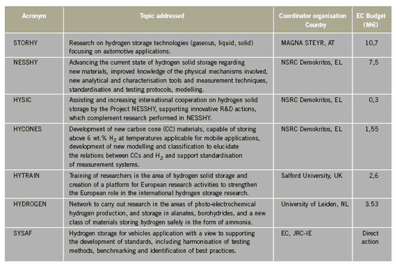
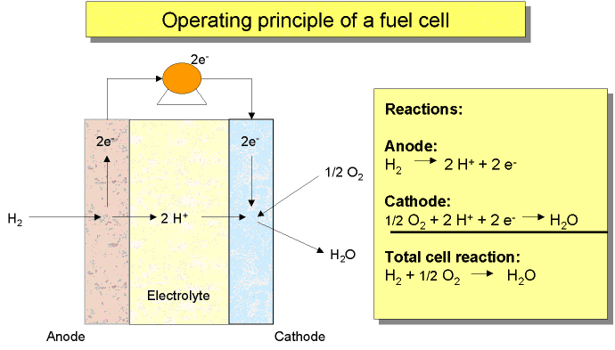
Storage - OtherThere are also other hydrogen storage methods, such as the following ones, (TzimasE:2003): Glass microspheres Tiny hollow glass spheres can be used for safely storing hydrogen. These glass spheres are warmed, and their walls permeability is increasing. Then, they are filled by immersion in high-pressure hydrogen gas. Following this, the spheres are cooled down to room temperature and the hydrogen is trapped inside the glass balls. Subsequent increase in temperature releases the hydrogen locked in these spheres. Hydride slurries These are a pumpable mixture of fine, solid metal hydride particles and a liquid (usually a mineral oil). Hydrogen is stored as a metal hydride in slurry with an organic carrier. It can be released from the metal complex through chemical reactions. Boron Nitride Nanotubes These are roughly equivalent to carbon nanotubes in terms of advantages, but are based on boron nitride rather than carbon. Bulk Amorphous Materials (BAMs) These are promising metallic materials based on multicomponent alloy systems, e.g. Ti-Al-Fe based BAM (maximum 6wt.%). They are loosely packed with porous defects (interstitial holes for hydrogen storage) of controlled size and distribution, in super cooled liquid phase. Hydrogenated amorphous carbon These are composed of stressed graphitic “cages”/nanotube sponges able to store 6-7wt.% hydrogen, are rather stable at 300şC with a potential for high hydrogen content and alleged potential to rapidly release hydrogen between 200-300şC. Chemical storage media (boron hydrides, amines, methanol, ammonia etc.) The hydrogen is often found in stable chemical compounds and it can then be released by a reaction the exact nature of which depends on the type of storage compound. Hybrids The option of combining storage solutions to create systems possibly achieving increased storage capacities and/or reduced improved safety levels is known as ‘hybrids’ (for example: hydrides/high pressure, porous/hydrides hybrid systems). EU Projects projects within Hydrogen storage 2002Lists of EU financed projects focused on hydrogen storage from 2002 – 2006 are given below. The topic adressed within each project is also given. The lists and additional information can be found in the EC report (EuropeanCommission:EUR22398EN:2006). References: {European Commission, Directorate-General for Research, Directorate-General for Energy and Transport} (2006) European fuel cell and hydrogen projects. RTD Info, EUR 22398 EN, Brussels.(BibTeX) Anode Reaction: H2 —> 2 H+ + 2 e- Cathode Reaction: ˝ O2 + 2 H+ + 2 e- —> H2O The basic principles of a fuel cell are illustrated in figure 1 The design of fuel cell systems is complex and can vary significantly depending upon fuel cell type and application. However, most fuel cell systems consist of the following basic components:
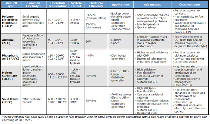
Fuel cells are generally categorized by their electrolyte. This material's characteristics determine the optimal operating temperature and the fuel used to generate electricity, and as a result, the applications for which these cells are most suitable (transport, stationary power and portable power). Each comes with its particular set of benefits and shortcomings. The main types of fuel cells are the following ones: I would like to have more detailed descriptions of these fuel cell (stacks) understood as “components”, again this is much like a description of technology
Table 1 shows the comparison of the main fuel cell technologies: Concerning fuel cells’s technology challenges, cost, durability and reliability are the major challenges to their commercialization. However, and according to the application, system size, weight, and thermal and water management are also additional barriers to the commercialization of fuel cell technologies. Monitoring and Control ComponentsChemical and physical processes involving hydrogen ˇV like any hazardous materials - must be monitored to ensure that they are within specific control limits (safe operation window). Hydrogen production units and applications often require a rather complex control system, due to varying conditions and operation modes including significant dynamic operation. Examples of such conditions are given below
Hydrogen systems usually involve a considerable number of components, such as valves, pressure relief devices, pressure and temperature regulators, check valves, filters and instrumentation. These components are crucial for the safety of the system. The components in a hydrogen system must be fabricated of materials, including soft goods such as seats and seals, that are compatible with the operating conditions, and with each other if more than one material is involved. The control system consist of measuring instrumentation - monitoring equipment such as flow meters, pressure and temperature transmitters, which in case of unacceptable process deviations will give a signal. This signal might give alarms in control room, or may initiate the control system e.g. to close or open valves dependent on the situation. Instrumentation provides a means to communicate with physical processes to obtain quantitative measurements of the behaviour or the state of the process. Controls provide a means to maintain or change the behaviour or state of a process. These are essential elements of a hydrogen system both for operation and safety of the system. It is of outmost importance that adequate instrumentation is designed so that the operation is within safe and acceptable limits. Usually, when designing a hydrogen system a systematic analysis is carried out, to check out possible deviations from normal operating conditions. These deviations are identified by using keywords (high/low/no/reverse flow/pressure/temperature/ignition sources etc.). Causes and consequences of these deviations are identified, and in case a hazardous or otherwise unwanted consequence, systems for detection and control of the hazardous deviation are included in design of the system. Usually redundant systems are included for deviations that might lead to a hazardous situation. Below some examples are given related to control components and situations when they are necessary. It must be underlined that this is just a very limited number of examples, and are not at all representative for the whole number of components or situations. Examples of control components:
These components have to be approved for the environments/installations where they will be installed, e.g. by CE-marking in Europe. Also the operator/owner of the installation is obliged by various regulations to assure that the components are installed/used in accordance with theis speicifications and limitations. Remote control of unmanned installations located in a public environment set high requirements to the control system ˇV to material properties and safe and reliable function. These examples represent situations coupled to control of the "internal" process operation. In case of a hydrogen leak to atmosphere, additional systems might be necessary to lead the system to a safe condition. Examples of components and measures are gas detection, fire detection, emergency ventilation, deluge and sprinkling, explosion venting etc. These measures are described in chapter 5 on mitigation. Also in such situations a well designed process control system will bring the process to a so-called "fail-safe" condition, for example emergency shutdown of process, ventilation of hydrogen under pressure to a non-hazardous location and purging of process components with inert gas. << | Content | >> |