|
BRHS /
OFD-Chapter 6Chapter 6. Safety measures
|
||||||||||||||||||||||||||||||||||||||||||||||||||||||||||||||||||||||||||||||||||||||||||||||||||||||||||||||||||||||||||||||||||||||||||||||||||||||||||||||||||||||||||||||||||||||||||||||||||||||||||||||||||||||||||||||||||||||||||||||||||||||||||||||||||||||||||||||||||||||||||||||||||||||||||||||||||||||||||||||||||||||||||||||||||||||||||||||||||||||||||||||||||||||||||||||||||||||||||||||||||||
|
References: BS 5925: 1991, Codes of practice for ventilation principles and designing of natural ventilation EUR 9689, Commission des Communautés Européennes, Eléments pour un guide de sécurité hydrogčne, Vol. 1 and Vol.2, 1985 FM Global, 2000, Property Data Sheets 7-91 « Hydrogen », September 2000 HSE 2003, Control of safety risks at gas turbines used for power generation, Plant and Machinery Guidance Note PM84, HSE Books (ISBN 0 7176 2193 6), 2003 Ivings, M.J. Lea, C.J. and Ledin, H.S., Outstanding safety questions concerning the use of gas turbines for power generation: Best Practice Guidelines for CFD, Health and Safety Laboratory Report No. CM/03/12, 2004 Ivings, M.J., Azhar, M., Carey, C, Lea, C., Ledin, S., Sinai, Y., Skinner, C., and Stephenson, P., Outstanding safety questions concerning the use of gas turbines for power generation: final report on the CFD modelling programme of work, Health and Safety Laboratory Report No. CM/03/08, 2004 Miles, S., HySafe Deliverable D49, 2006. NSS 1740.16, National Aeronautics and Space Administration, “Safety standard for hydrogen and hydrogen systems”, Guidelines for hydrogen system design, materials selection, operations, storage, and transportation. February 1997 |
Inerting is defined as the replacement of a sufficient proportion of oxygen contained in a gaseous atmosphere by an inert gas, to make it impossible for the atmosphere to be ignited or a flame to propagate. It is an important way to prevent the formation of explosive atmospheres, particularly for hydrogenated atmospheres. However, it must not be forgotten that inerting can be dangerous for workers because of the asphyxiating property of inert gas. Although we will focus here only on injection of a gaseous inert gas, it must be mentioned that in some applications, foams can be used. The latter has been designed for use on offshore installations for hot work, i.e. welding on process systems, (Anon, 1997).
The conditions which must be strictly complied with for a reliable and safe inerting are relative to the following features:
These conditions are fully described in the European document entitled “Guidance on inerting for the prevention of explosions” (prEN/TR 15281, 2005). The conditions for an hydrogenated atmosphere to be inert can be derived from a triangular diagram representing the Hydrogen-Air-Inert mixtures. Such a schematic diagram is given on Figure 1.
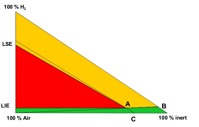
On this diagram, the apexes of the triangle correspond to one of the 3 pure gases:
The left side of the triangle corresponds to binary air-hydrogen mixtures : the currently accepted values for the Lower Explosion Limit (LEL) and the Upper Explosion Limit of hydrogen in air for normal atmospheric conditions have been placed on this side (LEL = 4 % vol. and UEL = 75 % vol.). The explosion area looks like a rectangular triangle (red area) : A is the apex of this area. Its lower side can be considered as parallel to the air-inert mixtures side. Its hypotenuse is almost parallel to hydrogen-inert mixtures side. The following lines have been drawn:
From the explosion diagram, the following concepts can be introduced
The Limiting Air Concentration (LAC) is the lowest air concentration of a hydrogen-air-inert mixture under which any hydrogen-air-inert mixture cannot be ignited: it corresponds to the air content of C and depends on the nature of the inert gas.
The Limiting Oxygen Concentration (LOC) is the lowest oxygen concentration of an hydrogen-air-inert mixture under which any hydrogen-air-inert mixture cannot be ignited and it can be derived from the concentration of oxygen in air : LOC = 0,209 LAC
The triangular diagram for ternary Hydrogen-Air-Inert mixtures comprises 3 coloured zones:
The ratio xinert/xH2, calculated from the co-ordinates of B, corresponds to the limiting ratio for absolute inert mixtures. As an example, taking nitrogen as the inert gas, the ternary diagram for Hydrogen-Air-Nitrogen mixtures is given in Figure A2 of the standard prEN14756 “Determination of LOC for gases and vapours” (prEN 14756, 2005) for 20°C and ambient pressure. This diagram has been experimentally determined in a 14 litre sphere according to EN 1839 standard “Determination of explosion limits of gases and vapours” (EN 1839, 2004) as described in (Schröder, 2002).
On this diagram, the following values can be derived:
Inerting consists in reducing the oxygen concentration of the atmosphere to be inerted to the lowest practical level, but it should always be less than the LOC. Typically for hydrogen, whatever the inert gas, an oxygen concentration equal to or less than 2% vol. should be used. There are several methods of inerting systems where hydrogen is to be used and the main ones are:
Further information on inerting methods in general are available in the in the CEN document (prEN/TR 15281, 2005). Where hydrogen is concerned, the requirements of the inerting system are more stringent due to several factors, including the extreme sensitivity of hydrogen to ignition, its very wide explosive limits, and its unusually low minimum oxygen for combustion. When inerting a system to contain hydrogen, it is best to use a technique which also leak tests the system as a routine part of the inerting. This can be accomplished by the use of a pressure or vacuum leak test as a part of the pressure or vacuum purging regime.
This involves pressurising the system with inert gas, and relieving back to atmospheric pressure. A pressure test can be incorporated by isolating the inert gas supply after pressurising, and determining whether the pressure falls after a period of time. As hydrogen has a very small molecular size, it is best to use helium when leak testing, as it has a similar molecular size.
When pressure-swing inerting a system, it is best to measure the oxygen concentration after inerting to confirm that the required oxygen level has actually been reached. Depending on the complexity of the system, such as a branched system or several interconnected vessels, it may be necessary to measure the oxygen concentration at several points within the system, to ensure that adequate mixing of the inert gas and the air initially present. This also applies when removing hydrogen from a closed system prior to the admission of air.
This uses exactly the same principles as the pressure-swing inerting. It involves the evacuation of a closed system and restoration to atmospheric pressure by the admission of inert gas. It is useful where a system can withstand vacuum but cannot withstand pressure, such as glass vessels.
Instead of a pressure leak test, a vacuum leak test should be applied, by isolating the vacuum from the system and measuring the rate of pressure rise. Even the best systems will eventually allow some air in, so provision should be made for vacuum systems to have the oxygen content measured, so that the system can be re-inerted before the inevitable air in-leakage makes the atmosphere within the system explosive.
The number of pressure-swing or vacuum-swing cycles can be calculated from the equation (1):
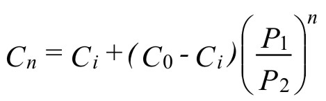 ( 1 )
( 1 )where:
n = number of pressure-swing or vacuum-swing cycles
Cn = oxygen concentration after n purges
Ci = oxygen concentration in the inert gas
C0 = initial oxygen concentration
P1 = lower purge pressure (absolute)
P2 = upper purge pressure (absolute)
Where systems can be neither evacuated nor pressurised, a flow-through technique can be used, which involves the replacement of an oxidant by a continuous flow of inert gas into a system which is vented to atmosphere. This is less efficient, and great care is required to ensure that adequate purging is achieved. A high flow rate is required to ensure adequate mixing.
The time required to purge a given volume can be determined from the equation (2) :
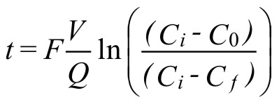 ( 2 )
( 2 )where:
t = time required for purging
V = system volume
Q = inert gas flowrate
F = safety factor for purging
Cf = oxygen content after flow purging
C0 = initial oxygen content
Ci = oxygen content of inert gas
t, V, and Q may be in any set of consistent units.
The inlet and outlet of the inert gas (place and geometry) should be chosen in order that:
When using a flow-through technique, the safety factor can be determined by measurement of the oxygen concentration in the gas stream being vented. Typical values of the factor F would be 1 for a single straight pipe fed at one end and vented at the other, to a value of 5 or more for a complex vessel system with poor mixing. Where a system is branched, it will be necessary to vent from the ends of all the branches to ensure that no pockets of oxygen remain. This makes flow purging the worst method of all.
This method relies on using an inert gas of significantly different density to that which is to be purged, and where significant mixing does not take place. It is used typically on the inerting of very large vessels, where it would not be possible to ensure adequate mixing if an inert gas of substantially the same density were to be used.
There is no safe inerting if the inert state of the system is not controlled and it is particularly true for hydrogen. There are two types of method for ensuring that the inert state of the system is maintained:
This method infers that the atmosphere is inert by reference to some other parameter, which allows an inference to be drawn that the atmosphere is inert. An example of this is where a system is pressure-swing inerted using Equation (1). If the number of purges is carried out correctly it can be inferred that the oxygen concentration will be correct. This is probably adequate for a simple single vessel which is pressure-swing purged. However, where a complex, branched system is pressure-swing purged, it is quite feasible that the ends of some of the branches will not be adequately purged, as the pressurising inert gas simply compresses the air trapped in the branch without mixing, so that when the pressure is released, the air expands again. Consequently, although the correct number of purges may have been applied, the system has not been fully inerted.
This can be improved by venting the pressurised system through each branch, to ensure that all the air is swept out. This can be proved by the use of a portable oxygen analyser used to measure the oxygen concentration of the gas vented from each branch. Once a system has been successfully inerted and the oxygen content found to be sufficiently low at all points within it, then it can be inferred that using exactly the same purging regime will also reproduce the same inert conditions. The disadvantage with inferring that the inerting regime is the same is that not all changes may be noticed and recognised. Hence there is a danger that the inerting may not be satisfactory, yet there will be no information to suggest that it is not successful.
This method actually measures the oxygen content of the atmosphere using a suitable oxygen sensor, and hence if there is any in-leakage of air, it is immediately detected. There are several potential problems with direct measurement. Firstly, there is the potential to measure the oxygen content at a single point, so that in a branched or complex system the sensor may not detect a change in oxygen content elsewhere in the system. This can be overcome by the use of multiple sensors. Where there are multiple sensors, these can be configured such that each reads continuously, or sequentially, so that each sensor is polled periodically. Any increase of oxygen is then detected with a maximum delay of the time between sequential readings.
The sensors have to be suitable for the duty that they have to perform, so that they are not poisoned by materials within the system. Similarly, blockages in the sensors may reduce their sensitivity or response time. Ideally, sensors should be calibrated regularly and a duplicate sensor should be used during the calibration. The major advantage with direct measurement is that oxygen ingress is usually detected very quickly, allowing safety systems to shut down the process or re-inert the system. However, where a system is automatic and reliant on the detectors working correctly, it will be necessary to ensure that the reliability is adequate.
Where hydrogen is routinely vented to atmosphere, it will be necessary to consider the potential for it to ignite. Unless it is diluted with inert gas until it is absolutely inert, it will be necessary to deal with the formation of an explosive atmosphere around the open end of the vent. As the minimum ignition energy is very low, it is likely that it will not be possible to exclude all potential ignition sources. Consequently, it will be necessary to assume that the hydrogen-air mixture will ignite, and suitable precautions will need to be taken to deal with the over-pressure produced. This may involve determining the extent of the dilution.
| References
prEN/TR 15281 “Guidance on inerting for the prevention of explosions” (2005) prEN 14756 “Determination of limiting oxygen concentration (LOC) for gases and vapours” Annex A2 (2005) EN 1839 “Determination of explosion limits of gases and vapours” (2004) Schröder, V. “Flammability limits of Hydrogen and Hydrogen/Methane mixtures” Nr. 253, NW Verlag, Bremerhaven 2002 (ISBN 3-89701-733-4) Anon, Nitrogen Foam Inerting, BJ Services, 1997 |
A recombiner is a device that promotes the recombination of hydrogen with oxygen - usually available as a constituent of air - forming water. As such, this device provides a hydrogen sink and may serve to avoid, remove or at least to slow down the formation of flammable mixtures caused by the accidental ingress of hydrogen into a closed area.
Recombiners can generally be classified into active and passive devices. Active recombiners use heat to initiate the conversion. Passive recombiners make use of the effect that hydrogen and oxygen react already at low temperatures and even beyond conventional concentration limits in an exothermal reaction in the presence of catalysts such as platinum or palladium. Appropriate measures (e.g. system design) need to be taken to prevent the system temperatures from exceeding the self-ignition temperature. This might cause an unintended ignition due to the exothermal reaction at elevated hydrogen concentrations. Without appropriate measures, the use of recombiners is limited to mixtures below the ignition limit (K. LEDJEFF, 1987).
As of today, hydrogen is primarily used in industrial scale in designated areas where the risk of formation of flammable mixtures may be reduced by design or where venting can easily be applied. As a consequence, only few specific application fields exist where recombiners are used. Only very few systems available off the shelf. With the use of hydrogen in ‚any surrounding in an increasing number of mobile applications an added need for specific recombiner systems may be expected.
Today, the main application fields are
New applications of recombiners or more generally catalytic recombination surfaces are also appearing, such as BMW’s boil-off management system.
During charging processes in batteries hydrogen and oxygen are produced and released. This may become a safety problem when dealing with large battery sections or when using batteries in a closed area like for example submarines.
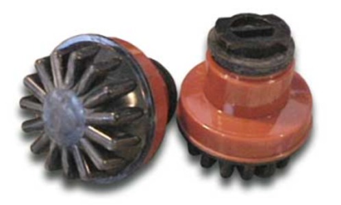 Recombiner systems have been developed by VARTA for batteries (K. LEDJEFF, 1982) as well as for use in submarines providing conversion capacities of 200 L/h (VARTA, year unknown). Recombiners for batteries, so-called ‘Hydrocaps’ are also available from Hydrocap Corp. (USA). These catalytic caps replace battery cell caps and reduce water-loss of batteries as well as the risk of gas explosions outside the battery.
 In nuclear reactors recombiners are used to remove hydrogen that is produced in service (Boiling water reactors (BWR), active recombiners) or possibly released during a severe accident (Light water reactors, passive autocatalytic recombiners).
Active thermal recombiners are used with gas capacities of 100 mł/h. The inlet gas is heated up to 700°C and above initiating the recombining reaction. The product gas is cooled before leaving the device. Thermal recombiners are manufactured by Siemens (Germany) and AECL (Canada).
Catalytic recombiners for use in nuclear reactors are manufactured by the companies Framatome-ANP (France), NIS (Germany), AECL (Canada), and Electrowatt-Ekono AG (Switzerland).
Catalytic recombiners need usually a minimum concentration of about 0.5 vol.% for start-up. As passive recombiners are self-feeding devices, the conversion rate depends on the self-generated throughput that depends on the catalyst temperature. In known systems typical flow velocities are between 0.5 and 1.0 m/s. In order to keep the system active over long periods some devices propose to be kept in a sealed environment to prevent the catalyst from being spoiled (poisoned) by the atmosphere.
Detailed information on the long term research (qualifying tests, experimental studies) that has been performed in the nuclear field with extensive bibliographical references are given in (W. ZHONG, 2001) and (E. BACHELLERIE, 2002).
|
Reference and sources K. Ledjeff. Elimination of hydrogen or oxygen from explosive mixtures by catalytic techniques. Int. J. Hydrogen Energy, Vol. 12, No. 5, pp. 361-367, 1987 K. Ledjeff, A. Winsel. Catalytic hydrogen/oxygen recombiner with self-limitation. J. Power Sources, Vol. 12, pp. 211-227, 1982 VARTA. Hydrogen elimination technology. Information brochure W. Zhong (Ed.). Mitigation of hydrogen hazards in water cooled power reactors. IAEA-TECDOC-1196, IAEA, Vienna, ISSN 1011-4289, 2001 E. Bachellerie et al. State-of-the-art report on passive autocatalytic recombiners - Handbook guide for implementing catalytic recombiners. EC Project PARSOAR, Contract FIKS-CT1999-20002, Technicatome company report, Technical note TA-185706 Ind. A., June 2002 |
There are three basic methods of protection:
The choice of a specific protection method depends on the degree of safety needed for the type of hazardous location (Zone 0, Zone 1 or Zone 2) in order to have the lowest probability value for an eventual simultaneous presence of an adequate energy source and a dangerous concentration level of an hydrogen/air mixture.
None of the protection methods can provide absolute certainty of preventing an explosion. The most efficient precaution is to avoid electrical apparatus in hazardous locations. Only when there is no alternative should this application be allowed. Other important factors to be considered are the size of the apparatus to be protected, the flexibility of the system, the possibility of performing maintenance, the installation cost, etc.
Explosion-proof enclosure: this protection method is the only one based on the explosion containment concept: in this case, the energy source can come in contact with the hydrogen/air mixture. But, even if the explosion is allowed to take place, it will remain confined in an enclosure specially designed to resist the overpressure, and thus preventing the propagation to the surroundings. This kind of protection is applicable only to equipments located in Zone 1 & 2, not in Zone 0. In Europe, CENELEC and IEC standards refer to this protection methods with the symbol “Ex "d" ”. The reference standard is the EN 50018 (EN 50018, 2000).
Pressurization protection method: pressurization is a protection method based on the segregation concept. This method prevents the penetration of the hydrogen/air mixture into the enclosure containing all the electrical parts that might generate sparks or dangerous temperatures. A protective gas (clean air or inert gas) is contained inside the enclosure, with or without continuous flow, in order to maintain a pressure slightly greater than the external atmosphere. This kind of protection is applicable only to equipments located in Zone 1 & 2, not in Zone 0. In Europe, CENELEC and IEC standards refer to this protection methods with the symbol “Ex "p" ”. The reference standard is the EN 50016 (EN 50016, 2002).
Encapsulation protection method: the encapsulation protection method is based on the segregation of those electrical parts that can cause the ignition of a dangerous mixture, by putting them in resins that are resistant to the specific ambient conditions. This technique is often used as a complement to other protection methods. This kind of protection is applicable only to equipments located in Zone 1 & 2, not in Zone 0. In Europe, CENELEC and IEC standards refer to this protection methods with the symbol “Ex "m" ”. The reference standard is the EN 50028 (EN 50028, 1999).
Oil-immersion protection method: the oil-immersion protection method is based on the submersion of all electrical parts in oil, which prevents the external flammable hydrogen/air atmosphere from going in contact with the electrical components. The most common application is for static electrical equipments, such as transformers, or where there are moving parts, such as transmitters. This method is not suitable for process instrumentation or for apparatus that requires frequent maintenance or inspections. This kind of protection is applicable only to equipments located in Zone 1 & 2, not in Zone 0. In Europe, CENELEC and IEC standards refer to this protection methods with the symbol “Ex "o" ”. The reference standard is the EN 50015 (EN 50015, 1998).
Powder-filling protection method: this protection method is similar to the oil-immersion one, except that the segregation is accomplished by filling the enclosure with powdered material so that an arc generated inside the enclosure will not result in the ignition of the dangerous atmosphere. The filling material that is generally used is quartz powder, and its granularity must comply with the standard. This kind of protection is applicable only to equipments located in Zone 1 & 2, not in Zone 0. In Europe, CENELEC and IEC standards refer to this protection method with the symbol “Ex "q" ”. The reference standard is the EN 50017 (EN 50017, 1998).
Increased safety protection method: this protection method is based on the prevention concept. Specific measures are applied to the electrical apparatus in order to prevent, with an high safety margin, the generation of excessive temperatures or of arcs and sparks inside and outside the apparatus during normal conditions. This technique can be used for the protection of terminals, electrical connections, lamp sockets and squirrel gauge motors, and is often used in combination with other methods of protection. This kind of protection is applicable only to equipment located in Zone 1 & 2, not in Zone 0. In Europe, CENELEC and IEC standards refer to this protection method with the symbol “Ex "e" ”. The reference standard is the EN 50019 (EN 50019, 2000).
Intrinsic safety protection method: intrinsic safety is the protection method most representative of the prevention concept and is based on the principle of limiting the energy stored in an electrical circuit. An intrinsically safe circuit is virtually incapable of generating arcs, sparks or thermal effects that are able to ignite an explosion of hydrogen/air mixture, both during normal operation and during specific fault conditions. According to the CENELEC EN 50020 standard, two categories of intrinsic safety (Ex "ia" and Ex "ib") are specified, defining the number of faults allowed for specific classifications and the safety coefficients to be applied during the design phase. The kind of protection Ex “ia” is applicable to equipment located in Zone 0, 1 & 2, while the Ex “ib” only to equipment located in Zone 1 & 2, but not in Zone 0. The reference standard is the EN 50020 (EN 50020, 2002).
Special protection method: originating in Germany and standardized in the United Kingdom, this protection method is not covered by any CENELEC or IEC standard and is not recognized in North America. It was developed to allow certification of apparatus that is not developed according to any of the existing protection methods, but can be considered safe for a specific hazardous location. This location must undergo appropriate tests or a detailed analysis of the design. The use of the special protection method is generally applied to Zone l & 2; however, Zone 0 certification is not excluded.
Mixed protection methods: in the process instrumentation field, the use of several protection methods applied to the same apparatus is a common practice. For example, circuits with intrinsically safe inputs can be mounted in pressurized or explosion-proof enclosures. Generally, this mixed system does not present installation difficulty if each of the protection methods is appropriately used and is in compliance with the respective standards.
Equipment categories The categories of a piece of equipment, suitable for installation in a potentially explosive atmosphere, indicate its design safety level and requirements, as well as its allowed applications and locations (Zone). According to the ATEX Guidelines (ATEX Guidelines, 2000), for Group II (defined as “equipment intended for use in places different from underground parts of mines, and from those parts of surface installations of such mines), the category depends on the localization of the product (Zone) and whether a potentially explosive atmosphere, is always present, or is likely to occur for a long or a short period of time. The following table shows the relationship between equipment category and safety requirements, as well as allowed applications and locations (Directive 1994/9/EC).
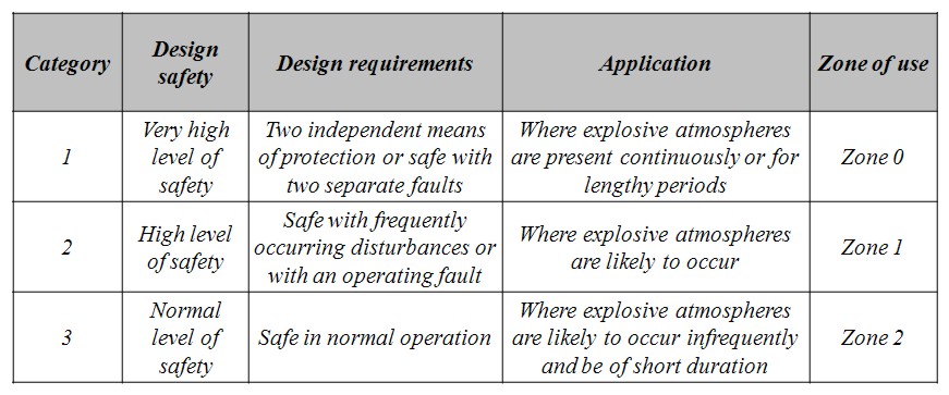
Table 0-1: ATEX Group II Categories and Application
|
References and sources EN 50018, Electrical apparatus for potentially explosive atmospheres - Flameproof enclosure 'd', CENELEC, 2000. EN 50016, Electrical apparatus for potentially explosive atmospheres - Pressurized apparatus "p", CENELEC, 2002. EN 50028, Electrical apparatus for potentially explosive atmospheres - Encapsulation “m”, CENELEC, 1999. EN 50015, Electrical apparatus for potentially explosive atmospheres - Oil immersion “o”, CENELEC, 1998. EN 50017, Electrical apparatus for potentially explosive atmospheres - Powder filling “q”, CENELEC, 1998. EN 50020, Electrical apparatus for potentially explosive atmospheres – Intrinsic safety “i”, CENELEC, 2002. ATEX Guidelines (First Edition), Guidelines on the application of Council Directive 94/9/Ec Of 23 March 1994 on the approximation of the laws of the Member States concerning equipment and protective systems intended for use in potentially explosive atmospheres, May 2000. Directive 94/9/EC of the European Parliament and the Council of 23 March 1994 on the approximation of the laws of the Member States concerning equipment and protective systems intended for use in potentially explosive atmospheres, Official Journal L 100, 19/04/1994 P. 0001 - 0029. |
A hot surface can exist during normal operations or may occur as a result of mechanical distress (friction) in machinery such as pumps or motors. “Hot surfaces” includes both hot spots and hot plate ignition. Ignition of a gas or vapour air mixture by a hot surface is a manifestation of auto-ignition. A boundary layer of this mixture in contact with the hot surface if heated sufficiently will result in a spontaneous ignition.
Apart from hot surfaces, open flames (and hot work) can also trigger an explosion. They will be dealt with in this chapter.
For ignition to occur on a hot surface, its temperature shall be greater than the gas auto-ignition temperature. Therefore, for hydrogen, hot surfaces or hot spots temperatures shall not go beyond 560°C. This value is rather high in comparison with most combustible gases and vapours. However, unlike most combustible gases, experience has shown (MECHEX EU project) that hydrogen/air ignition by hot surfaces will happen at temperature very close to the auto-ignition temperature even for a few mm2 hot surface .
The control of hot surfaces during normal operations necessitate the selection of electrical and non-electrical equipment with care. Electrical and non-electrical equipment marking incorporates a temperature class (ranging from T1 to T6) as detailed in the table below.
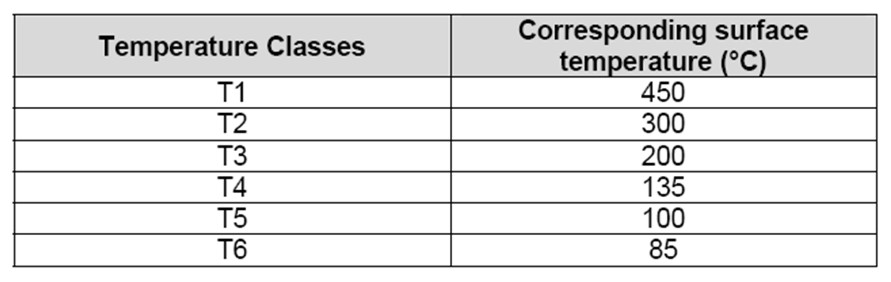
Table 2: Class temperature according to EN5014 or EN 60079-9?
As an example, surface temperatures of equipment belonging to the class T2 does not go beyond 300°C. In order to prevent ignition by hot surfaces, the surface or hot spot temperature of any equipment should not exceed the gas auto-ignition temperature. Hence, the maximum tolerable surface temperature when handling hydrogen is around 580°C. Therefore, equipment belonging to class 1 and above are appropriate for hydrogen use.
As far as mechanical ignitions are concerned, they are generally the result of mechanical distress (friction) under abnormal or fault conditions. Analysis of the physical processes that lead to mechanical ignition shows that there are at least three key stages from production of heat, transfer of heat to the surrounding explosive atmosphere and finally the ignition itself (Hawksworth).
In general, the friction processes that need to be considered are rubbing (long duration friction between surfaces producing a hot surface), grinding (long duration friction producing hot surfaces and sparks) and impact (short duration friction producing short duration transient hot surfaces and sparks), or a combination of these.
Ignition by friction clearly depend on the temperature generated in the contact zone. For grinding and rubbing, the temperature at contact point depends on the rubbing speed and the contact pressure. Tests have demonstrated ignition down to speeds of 0.7 m/s (0.7 kW friction energy). In that case, ignition is triggered by the hot surface, few sparks being produced under these low speed conditions. (Hawksworth).
Control of mechanical ignition therefore necessitates careful design of equipment. It includes for instance to limit the rotating speed, to provide a sufficient distance between fixed and rotating parts. Temperature sensors may also be installed on mechanical equipment to detect any temperature deviation that necessitates to switch off the equipment. European standards propose various design options to prevent ignition by mechanical equipment as detailed in the table below.
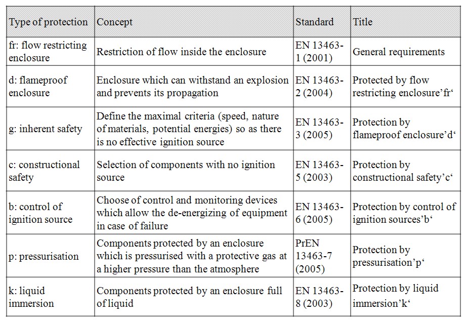
Table 3: Type of protection for mechanical apparatus used in potentially explosive atmosphere
For impact, experience indicates that impact energies as small as a couple of Joules are sufficient to ignite a hydrogen/air mixture. If we admit this rough evaluation it means that a solid object falling from man height could cause hydrogen ignition (Proust). Therefore, sufficient impact temperature can eventually result from the use of hand tools (falling tool, hammer…).
The use of hand tools made of bronze enriched with few percent of beryllium (to give them sufficient hardness) are known as spark free tools. They are of common use in gas industries (natural gas distribution). However, the absence of spark does not guarantee that hydrogen/air explosive atmosphere will not be ignited (guide hydrogčne). Indeed, the temperature reached at the contact point is the main driving cause to trigger an ignition (even when sparks are produced).
Therefore, it is a very delicate issue to select the appropriate hand tool in location where hydrogen is handled. As a consequence, whatever the tool used, it is always recommended to purge hydrogen before any intervention. Tools coated with shock absorbing materials can be a better option (as long as the coating material can not give rise to electrostatic sparks). Floor can also be covered with shock absorbing materials.
Finally the use of aluminium in contact with steel must be prohibited due to the highly energetic reaction that can takes place whenever aluminium gets into contact with rusty steel.
Hot work like grinding ignition mechanisms have been detailed above. The only difference between hot work and grinding ignition mechanisms being that hot spots and sparks are not generated by a process mechanical failure but by human activity. Whenever hot work takes place (welding, grinding…) a hot work permit should be required. This permit assesses any fire or explosion hazards in connection with the planned work and proposes prevention and protection means for risk control. Prevention typically implies to switch of any gas supply and to purge equipment… Examples of protection means are to have fire fighting equipment available and organising beats after work completion.
Beyond the delivery of a “hot work permit” people involved in hot work should be appropriately trained.
|
References S Hawksworth & all, « Ignition of explosive atmosphere by mechanical equipment », CEN/TC 305/WG 2 N0433, SYMPOSIUM SERIES No. 150, 2005 EN 60079-9 (2004) , « Electrical apparatus for explosive gas atmosphere : General requirements ». Norme EN 50014 : 1997 – Matériel électrique pour atmosphčres explosibles – Rčgles générales EN 50281-1-2 : Sélection, Installation et entretien : Tmax admissible = 2/3 Tnuage ATEX Guide, TÜV Rheinland France Eléments pour un guide de sécurité hydrogčne – Expérimentations spécifiques, Choix d’appareils adaptés – Volume 1 – Annexe 1 : Protection contres les étincelles d’origine mécanique, Rapport EUR9689 FR, année 1985 |
Different guidelines exist (CLC/TR 50404, NFPA 77) treating practical solutions in order to avoid the charge generation and accumulation phenomena and thus electrostatic discharge in various industrial situations. In a non-exhaustive way, we can recall the principle measures to adopt:
The first stage consists in avoiding, as far as possible, electric charge generation by one of the phenomena previously mentioned.
For the majority of nonconductive liquids, it is recommended not to exceed 1 m/s transport speeds, either by decreasing the flow of the pump, or by increasing the pipe diameter. This value will have however to be checked before its application in the case of hydrogen.
In the case of particles contained in a gas flow, it is not possible to prevent the electrical charging of these particles, but it is possible to prevent the accumulation phenomenon.
The second stage consists in avoiding the use of insulating materials (supports, valves, coatings, etc) and in putting all the elements of the installation at the same potential and in grounding them.
The use of insulating materials must be avoided, as far as possible, whatever its size. Indeed, a simple bolt has a capacity of 1 PF and its setting with a potential of 10 kV would be enough to produce a spark discharge of 50 J, sufficiently to ignite an air-hydrogen ATEX.
In the same way, the use of certified materials according to the category corresponding to predefined ATEX zones allows the use of safety material. Thus, a material of category 1 and valid for IIC gas group, to which hydrogen is attached, should not include surfaces higher than 4 cm2 of insulating material (according to EN 13463-1 standard).
Bonding will have to be made so as not have an insulated element able to accumulate electrical charges. The system will be connected to the ground in such way that the leakage resistance between an unspecified point of the installation and the ground will not exceed the threshold of 106 Ω. In practice, for the metal elements, this resistance is normally much lower than this value.
Taking into account the electrostatic risk from the electrical charged operators in the hydrogen industry is to be considered as for the semiconductors industry. Indeed these are very sensitive to the electrostatic discharges which can strongly damage them. Thus, the same type of equipment can be carried by the involved personnel: grounded bracelet, conductive shoes, antistatic fabrics, etc. The leakage resistance between a person and the ground should not exceed 108 Ω. However, it is important to note that the overriding principle with regard to personnel is that wherever possible, all precautions should be taken to ensure that they do not operate in an explosive atmosphere, or in an area where an explosive atmosphere is likely to occur.
Other measures (air humidification, ionisation), in order to limit the charge accumulation and discharge phenomena, exist but are not easily applicable in the case of installations handling liquid or gaseous hydrogen.
All measurements described in this paper would not be enough to prevent and protect the industrial installations from the electrostatic risk if the personnel were not trained accordingly and if technical improvements were not checked periodically. This step fits fully in the logic of the risks analysis required by 1999/92/CE European Directive transposed in each member state of the EU. The taking into account of the electrostatic risk is explicitly required there (1999/92/CE Directive, Annexe II §2.3), as well as the staff training concerned with ATEX risks (1999/92/CE Directive, Annexe II, §1.1).
The electrostatic charge and discharge phenomena are well-known for the majority of the combustible materials as for the various manufacturing processes and were briefly detailed above.
But the risks related to the intrinsic data of hydrogen (low MIE, low conductivity for liquid hydrogen) have not been studied in detail yet. The risks related to the accidental leak of compressed hydrogen is, a priori, one of the most probable sources of ignition for the ignition of air-hydrogen ATEX (Astbury and Hawksworth, 2005), but that remains to be shown.
The following of safety procedures and training of professional personnel involved in the handling of hydrogen systems are probably the most important of prevention measures to reduce the occurrence of and potential consequences of incidents or accidents. Such procedures and training exist today in the chemical industry where hydrogen is produced, handled, stored and transported. Similar procedures are therefore to be developed for new applications of hydrogen such as transport or energy conversion, for professionals who come into contact with hydrogen. For the public, specific education courses are needed to address the specific properties of hydrogen, compared to other more familiar fuels such as natural gas or gasoline. Having a basic understanding of how hydrogen behaves when accidentally released into the environment is a prevention measure that all stakeholders of hydrogen must follow.
All measurements described in this paper would not be enough to prevent and protect the industrial installations from the electrostatic risk if the personnel were not trained accordingly and if technical improvements were not checked periodically. This step fits fully in the logic of the risks analysis required by 1999/92/CE European Directive transposed in each member state of the EU. The taking into account of the electrostatic risk is explicitly required there (1999/92/CE Directive, Annexe II §2.3), as well as the staff training concerned with ATEX risks (1999/92/CE Directive, Annexe II, §1.1).
The electrostatic charge and discharge phenomena are well-known for the majority of the combustible materials as for the various manufacturing processes and were briefly detailed above. But the risks related to the intrinsic data of hydrogen (low MIE, low conductivity for liquid hydrogen) have not been studied in detail yet. The risks related to the accidental leak of compressed hydrogen is, a priori, one of the most probable sources of ignition for the ignition of air-hydrogen ATEX (Astbury and Hawksworth, 2005), but that remains to be shown.
Detection may consist in supervising an unattended site, or in monitoring signals that cannot be perceived by attending employees, with the aim of producing an action before an accident escalates. In the case of hydrogen fires, detection can fulfil both requirements. The major hazards due to an unwanted release of hydrogen relate to the build up of explosive conditions. In this respect, hydrogen is potentially more hazardous than other conventional fuels (methane, propane) or their vapors (gasoline) in most confined situations because of its high flammability, wide detonability ranges and its low ignition energy (CracknellRF:2002). Although its high buoyancy means that the risks of an unwanted release are likely to decrease rapidly to acceptable levels in outdoor situations and/or in areas where there is adequate ventilation, the deployment of an adequate system for the detection of explosive atmospheres should always be taken into consideration as a possible safety measure.
In regulatory terms, the issue of an explosive atmosphere is covered within the existing legislation for the safe use of flammable and explosive gases in general. Alongside other protection measures, the European Parliament and Council Directive 1999/92/EC on the Minimum Requirements for Improving the Safety and Health Protection of Workers potentially at risk from explosive atmospheres (Directive:1999:92:EC:2000) prescribes that “Where necessary, workers must be given optical and/or acoustic warnings and withdrawn before the explosion conditions are reached”. It follows that the necessity of installing a detection system should be estimated as part of a preliminary analysis of the operational hazards posed by the use of flammable gases. The point is further detailed in a subsequent Communication of the European Commission (COM:2003:515final) on the good practice for implementing the Directive, which states that “Concentrations in the vicinity of a plant can be monitored e.g. by means of gas alarms”. For such alarms to be used, the substances likely to be present, the location of the sources, maximum source strength and dispersion conditions must be known in sufficient detail and the instrument performance must be appropriate to the conditions of use, especially with regard to response time, alarm level and cross-sensitivity. Failure of individual functions of gas alarm systems should not lead to dangerous situations and the number and location of measuring points must be chosen to allow the anticipated mixtures to be detected quickly and reliably. Last but not least, gas alarms for use in hazardous areas must be approved and suitably marked as safe electrical equipment according to the European Directive 94/9/EC (Directive:94:9:EC:1994), which in turn is supported by a number of European standards prepared by CENELEC (EuropeanCommission:ATEXGuidelines:2007) annexes 5-7. While ensuring the safety of industrial operation in the presence of flammable gases is a well-recognized issue for which a number of established technologies can be used, there is a need to reconsider existing knowledge of hydrogen detection in the light of a future hydrogen economy. A wide variety of novel applications could be in sight, some of which may bring hydrogen much closer to the general public than it has ever been before, thus requiring hydrogen sensors to be as ubiquitous as computer chips in our society (DiMeoFJr:2000). Both, the U.S. Department of Energy (DoE) and the European Hydrogen Fuel Cell Platform (HFP), have been identifying new directions for hydrogen sensor development, envisaging innovation in both materials and concepts for applications ranging from large-area physical sensing to in-situ detection of leaks from portable devices (HFP:StrategicResearchAgenda:2005). Efficiency over a wide range of hydrogen (and oxygen) concentrations, low sensitivity to gaseous contaminants and poisoning are outstanding requirements, along with the possibility to efficiently integrate “intelligent” sensing devices into hydrogen systems, so that safety or emergency measures can be activated automatically where needed.
Several types of hydrogen sensors are in use, selected according to the operating conditions. Electrochemical, catalytic and thermal conductivity sensors are mainly used in industries where hydrogen risk is present. Semi-conductor-based sensors are most often used in research laboratories, whereas MEMS's (Micro Electro Mechanic System) are used in the aeronautic and space travel industries. The operating principles of commercially available sensorsand some other sensors which are under development are briefly described below.

The working principle is amperometry, i.e. the measurement of current driven by redox- (reduction-oxidation) reactions. The process is based on an electrochemical cell covered by a semi-permeable, selective membrane which enables the exclusive diffusion of hydrogen. The diffusion rate through this membrane is proportional to air temperature and to the partial pressure of hydrogen (and therefore to its concentration in air). Once it has diffused through the membrane, hydrogen comes into contact with the boundary layer between the membrane and the electrolyte which consists of sulphuric acid. The hydrogen is instantly ionised at the solid-liquid interface of a platinum catalytic electrode (working electrode). This ionisation enables a redox reaction with the second electrode (auxiliary electrode) consisting of platinum oxide. These reactions cause a potential difference between the electrodes which enables the hydrogen concentration to be determined by a non-linear correlation. The reaction products generate charge barriers which tend to restrict the reaction. To improve the stability and the reproducibility of the measurement, a third, chemically non-active electrode is added to the cell. A potentiostat (created by using an operational amplifier) is applied to maintain the potential of the working electrode at the same value as this third electrode, called the reference electrode. The lifetime of the amperometric cell is limited by a dry-out effect of the electrolyte which is strongly influenced by its exposure to certain operating conditions, especially raised temperatures. (AccorsiA:1994),(JamoisD:1997)

The detection principle is based on combustion heat measurement of flammable gas at the surface of a metallic catalyser. This means that a pearl covered with a catalyst (called a pellistor or catalytic pearl) or even a platinum filament is heated by the Joule effect while its electric power consumption is measured. Combustion of gas molecules at the element surface causes an increase in its temperature and therefore a change in its resistance. This resistance modification creates an imbalance in the Wheatstone bridge where the measurement element is inserted. Hydrogen concentration in air is linearely correlated to the imbalance of the bridge. To overcome the influence of variations in temperature and room humidity, a second element, similar to the one used for the measurement, but with a non-catalytic surface, is inserted into the Wheatstone bridge. In the absence of combustible gas, each of the two elements undergoes identical resistance variations and the bridge remains balanced. (AccorsiA:1994),(JamoisD:1997),(MoliereM:2005)

Heat conduction sensors use the high thermal conductivity of hydrogen gas. A material heated by the Joule effect is stabilised at a temperature which depends on the electrical power provided and thermal exchanges with the gaseous environment. A change in the composition of the atmosphere causes a change in the sensor temperature. The derivative of this temperature change, which varies the electrical resistance of the element, is linearly correlated to the concentration of hydrogen gas in air. For the measurement, a metallic wire conductor coated with chemically inert material is exposed to the gas probe. A second identical wire conductor is exposed to a reference atmosphere for temperature compensation. The electrical resistance variation is also measured using a Wheatstone bridge. Signals caused by the varying thermal conditions are weaker than the signals of catalytic sensors. (AccorsiA:1994)

The support material of the redox-reaction is no longer a metal, but an n- or p-type semi-conductor of metal oxide (SnO2, ZnO, etc.). Its conductivity is caused by shortages of oxygen (oxide not exactly stoichiometric). These redox reactions, or simply adsorption reactions on the surface, change the material resistance by modifying the number of oxygen shortages. The material is heated, similar to the catalytic pearls, but the measurement is different: The resistance variation of the material itself is measured rather than that of the heating element, which is linked to hydrogen concentration by a non-linear correlation. (AccorsiA:1994)

This sensor type is based on a metal oxide field effect transistor. Hydrogen diffuses into the transistor bulk, and its electrical properties change, dependent on the hydrogen concentration. Hydrogen presence induces an increase of the threshold voltage and a decrease of transconductance in an electrical connection as shown in Fig. 5. These transconductance changes are linked to hydrogen concentration by a non-linear correlation.

This sensor type consists of a catalytically active palladium surface. Hydrogen is adsorbed, dissociates to hydrogen atoms and generates palladium hydride, which has a higher electrical resistance than the pure palladium. This resistance change, which is linearely correlated to hydrogen concentration, is then measured. (TanOK:1999)
Micro electro mechanic systems combine calculators and miniscule devices such as sensors, valves, gears, mirrors and actuators loaded on a semi-conductor chip. The “detector” chip comprises

The operating principle of the Schottky diode is the following: the palladium enables the adsorption and the dissociation of the hydrogen molecule into hydrogen atoms. The hydrogen atoms diffuse through the palladium up to the PdCr interface and modify the surface charge. This change is detectable by measuring the voltage-current pair and is dependent on the hydrogen concentration by a non-linear correlation. In the case of a resistive sensor, the formation of palladium hydrides (caused by the adsorption and the dissociation of the hydrogen molecule into hydrogen atoms) increases the resistance compared to the pure palladium. (ChengSY:2003),(KimJ:2003),(ChenHI:2001)
Hydrogen detection technologies can generally be divided into non-optical and optical based technologies. The following section gives a survey on both, starting with non-optical technologies (TobiskaP:2001),(TanOK:1999). Recent technologies are
The development of semi-conductor and Schottky diode sensors mainly aims to improve the selectivity of the different layers as well as testing new metallic substrate–deposit combinations. Although these technologies are available on the market, research continues in order to reduce drift and to increase selectivity. The operation of semi-conductor and Schottky diode technologies is described above. Among others the operating principles of palladium wire network based sensors and surface sound wave sensors on a nano-structured sensitive layer are described. Emerging optical technologies mainly use fibre optics combined with hydrogen-sensitive coatings to measure hydrogen concentrations. (BaoX:1995),(BillingtonR:1999),(GlennSellarR:2003)
These sensors consist of a network of 20 to 100 palladium nano or mesoscopic wires. These networks of palladium nano-wires are prepared by electro-deposition on a graphite surface and transferred onto a glass slide covered with a cyanacrylate film. The nano-wires are then connected on either side by silver contacts. These palladium nano-wires are in fact “broken” and do not conduct the current. In the presence of hydrogen, the palladium swells slightly, and the nanoscopic spaces or “breakages” are “repaired”, enabling the passage of electric current. The resistance change depends on the hydrogen concentration, in a concentration range from 2 to 10%. In order to operate these sensors require a permanent power connection, and may even need to be heated. (FavierF:2001),(MatsumiyaM:2003)
A surface acoustic wave sensor is built around two interconnected transducers placed on the surface of a piezoelectric substrate. By connecting alternating current to the metallic conductors of the entrance transducer, an alternation of compressions and expansions occurs which generates a surface wave. This wave moves towards the second transducer to be converted back to an electric signal. During the transit between the two electrodes, it is possible to influence the wave by using a nano-structured sensitive net, which consists of the same palladium wire network mentioned in the previous paragraph. This network represents disruptions for the wave conducting surface and varies its physical characteristics (density, rigidity, electric conductivity, thickness) with absorbed hydrogen, which itself depends on the hydrogen concentration present. These disruptions lead to hydrogen concentration dependent phase speed and attenuation variations of the surface acoustic waves. Temperature dependencies can be minimized by comparison with the output signal of a second, identical sound wave sensor without an H2-sensitive Pd network.

This type of interferometric hydrogen sensor is based on a multi-modal fibre optic with a palladium micro-mirror. Hydrogen is absorbed by the palladium micro-mirror located at the end of the fibre. The optical and electric properties of the palladium change. Consequently, the reflected wave is modified whereas the incident wave remains the same. (BevenotX:2000)

Tungsten trioxide (WO3) shows hydrogen concentration dependent changes in its refractive index (BensonDK:1999), which leads to changes in the reflected light intensity. Resulting intensity variations of the reflected beam can be interferometrically detected.

The sensitive area is a fibre section covered with a thin palladium film. Light waves passing the fibre cause evanescent waves on the fibre core surface. Since the core of the fibre is covered with a palladium layer, the evanescent fields are altered. When hydrogen is absorbed by the palladium film, the refractive index of the Pd coating changes by reduction. This change in the refractive index modifies the absorption of the guided light, which can be detected by monitoring the light intensity via interferometer techniques like Fabry-Perot. (TabibAzarM:1999),(UttamchandaniD:1999),(KazemiAA:1999),(MaN:1999)

A Bragg network causes periodic or aperiodic disruption of the effective absorption ratio or of the effective refractive index of a fibre-optic cable. Predetermined light wavelengths are reflected by the Bragg network while all other wavelengths pass through it. In this sensor, which operates with UV light, a mechanical stress develops which is caused by the palladium layer when it absorbs hydrogen. This stress stretches or compresses the Bragg network and therefore the wavelengths or optical lengths of reflected or transmitted light. Where several Bragg networks with different lattice constants are used, several hydrogen sensors can be multiplexed on a single fibre. (SutapunB:1999)

This type of non-electric indicator consists of a thin film coating or a pigment of a transition metal oxide such as tungsten oxide or molybdenum oxide with a catalyst such as platinum or palladium. The oxide is partially reduced in the presence of hydrogen in concentrations as low as 300 parts per million and changes from transparent to a dark color. The color change is fast and easily seen from a distance. In air, the color change reverses quickly when the source of hydrogen gas is removed, in the case of tungsten oxide, or is nearly irreversible, in the case of molybdenum oxide. The partially reduced transition metal oxide becomes semi conductive and increases its electrical conductivity by several orders of magnitude when exposed to hydrogen. The integration of this electrical resistance sensor with an RFID (Radio Frequency IDentification) tag may extend the ability of these sensors to record and transmit a history of the presence or absence of leaked hydrogen over long distances. Over long periods of exposure to the atmosphere, the indicator’s response may slow due to catalyst degradation. Current emphasis is on controlling this degradation. Chemochromic sensors and their derivatives like paints, tape, cautionary decals and coatings for hydrogen storage tanks may be used to complement conventional electronic hydrogen sensors, or as a low-cost alternative in situations where an electronic signal is not needed for visual human surveillance. (HoaglandW:2007)
Table 1: typical hydrogen sensor properties
| Sensor Type Standard / Special | Hydrogen Concentration Range | Cross Sensitivity / Selectivity | Accuracy | Long-Term Stability | Response Time | Warm-up Time | Power Consumption | Costs |
| Electrochemical | 10,000 ppm | CO / high selectivity | 10% | - | < 1 min | 0.5 h | 1 mW | low |
| Catalytic bead | 100% LEL | Hydrocarbons, Combustible Gases & Vapours / low selectivity | 10% | o | < 0.5 min | 5 min | 1 W | medium |
| Heat Conduction / Catharometer | 100% Vol. | CH, CO2, He, Ar, Ne, SF6 / high selectivity | 0.5% | + | < 0.5 min | 1 min | 10 min | medium |
| Semiconductor | 100% LEL | low selectivity | 5% | -- | < 0.5 min | 5 min | 25 mW | very low |
| Field Effect Transistor | 30,000 ppm | high selectivity | 10% | - | < 10 s | 1 min | - | medium |
| Ultrasonic | 100% Vol. | low selectivity | 10% | o | 1 µs | 1 s | - | medium |
| Gas Chromatograph | 50% Vol. | very low / very high | 10% | - | 1 min | 3 h | - | very high |
| Mass Spectroscopy | 100 ppm -100% Vol. | very low / very high | 10% | + | 10 ms | 6 h | - | very high |
| MEM's | 10ppm -100% Vol. | low selectivity | 10% | - | - | - | - | high |
As a colourless, odourless and tasteless gas, hydrogen cannot be detected by human senses. Means should therefore be provided to detect the presence of hydrogen in places where leaks and/or accumulations may occur. The hydrogen detection system should be compatible with other systems such as those for fire detection and fire suppression. Hydrogen detection devices themselves should not be a source of ignition and the response times of these devices should be as rapid as possible. Some important performance factors to be considered when selecting a hydrogen sensor for a particular application include:
The correct location of reliable sensors is crucial for timely detection and warning of hydrogen leaks before an explosive mixture is formed. Recommended locations (ISO/TR 15916, 2004 (ISO:TR:15916:2004E)) for sensors include the following:
A generally accepted and commonly used concentration level for alarm activation is 1 % hydrogen (volume fraction) in air, which is equivalent to 25 % of the lower flammability limit. This level should normally provide adequate time for an appropriate response to be initiated, such as a system shutdown, evacuation of personnel or other measures where necessary. In designing a reliable hydrogen detection and monitoring system, the following recommendations have been made by NASA 1997 (NASA:NSS:1740:16:1997):
At a European level, and to the knowledge of the authors, no EN standard or recommendation for detection layouts specific to hydrogen systems has been made publically available so far. However, an obligation is posed under the ATEX directive (Directive:94:9:EC:1994) for the necessary instructions for detection or alarm devices for monitoring the occurrence of explosive atmospheres to be provided in the appropriate places. The European Standard EN50073 (EN:50073:1999) supporting the Directive provides details of the criteria for the selection, installation and placement of combustible gas sensors, which are essentially coherent with the information laid down in the previous paragraphs of the EN 50073. The international standard IEC 61779-6 (EN:61779-6:1999), very similar to the EN 50073, also provides a two-pages document in the annex that summarizes the above points in the form of a typical environmental and application check-list.
A detector includes two elements: a sensor and a transducer. The sensor is the sensitive element responsible for converting a physical value (e.g. gas concentration) into a useful output signal. The transducer turns the output signal into meaningful information displayed by the user interface. Sensor or / and transducer ageing may cause a drift with time. Maintenance is therefore essential to maintain the high performance level required for a safety applications.
Regarding maintenance, detectors should be:
Maintenance intervals depend on both the context of use and the type of detector involved (detection technique, portable or fixed detector…). The best way to determine the maintenance interval for a detector is based on experience gained through the use of this detector. For new installations, it may be wise to carry out maintenance frequently at first (perhaps weekly), increasing the time intervals (to, perhaps, monthly) as confidence grows on the basis of the maintenance records of the installation concerned. Information on the maintenance protocol should be found in the user manual. IEC 61508 (EN:61508-1:2001) also deals with the need for periodic maintenance.
Hydrogen burns with very pale blue flames and emits neither visible light in day time (solar radiation can overpower the light from a hydrogen flame) nor smoke (it produces water when it burns in air) unless, for example, sodium salt is added or dust particles are entrained and burned along with the combustible mixture. Compared to hydrocarbon combustion, hydrogen flames radiate significantly less heat and so human physical perception of this heat does not occur until direct contact is made with the flame. A hydrogen fire may therefore remain undetected and propagate despite human direct monitoring in areas where hydrogen can leak, spill or accumulate and form potentially combustible mixtures. Hydrogen fire detectors ensure that immediate action is taken in these situations. Hydrogen fire detectors can be either stationary for continuous monitoring of remote operations or portable for field operations.
For an efficient and reliable use, a hydrogen fire detector should fulfil the following criteria:
In terms of performance, its ability
should be considered when installing a hydrogen flame detector.
For instance, NASA (NASA:NSS:1740:16:1997) indicates that a fire detection system should at least be capable of detecting, at a minimum distance of 4.6 m, the flame from the combustion of 5.0 l/min of gaseous hydrogen at NTP flowing through a 1.6 mm orifice to produce a 20 cm high flame.
A hydrogen fire can potentually be detected by using thermal detectors (such as rate-of-temperature-rise or overheat detectors) to pick up radiative, convective or conductive heat. These reliable detectors of various types are suitable for hydrogen fire detection as long as they are located very near to where the fire breaks out. Other common fire detector types such as those with ionising cells, are not appropriate for detecting hydrogen fires.
Though hydrogen fires tend to emit radiation over a broad range and are not characterised by extreme peaks, hydrogen fire detectors can also rely on UV and IR light detection. Beside the radiation itself, hydrogen flames can be indirectly visible by their strong heat effect and turbulence - “heat ripples” - of the surrounding atmosphere. Optical flame detectors detect specific spectral radiation emitted during the combustion process by the various chemical species (ions, radicals, molecules) that are either intermediates or final products of combustion. Chemical species emit radiation at wavelengths characteristic to the particular species.
These detection techniques assume that no interfering shield is placed between the flame and the UV / IR detector. Though optical techniques are available to pick up these various wavelengths, the main challenge consists in ditinguishing hydrogen flame signals from other potential sources that emit signals with a similar frequency and intensity.
UV systems are preferable to IR systems because they are extremely sensitive. In addition, the probability of encountering an interfering signal is lower as long as UV detectors are shaded from sun light. Drawbacks are on the one hand the cost and on the other hand the reduced efficiency with liquid hydrogen flames, as fog blocks UV rays. The same applies whenever fog is present. False alarms can be triggered by random UV sources such as lightning or arc welding.
The ability of the detector to discriminate sunlight-induced UV radiation from hydrogen flames to avoid false alarms is the main challenge. Various techniques can be applied:

It was mentioned above that fog may hinder UV transmission to the sensor cell. IR detectors are not affected by this issue. In addition, hydrogen flames emit sufficient IR for their detection with IR sensors. The main challenge remains the same as before: i.e. discrimination between IR related to a hydrogen fire and IR from the sun, any light sources or any hot materials. IR sources powered with alternating electric currents can be filtered due to their own 100 Hz modulated signal. However, neither hot bodies nor sunlight display a modulated signal that can be picked up and filtered. A solution consists in focussing on the 1.7 µm wavelength that corresponds to a peak emission of steam, bearing in mind that the atmosphere absorbs sun-emitted IR wavelengths between 1.81 & 1.88 µm and between 2.55 & 2.9 µm. The 1.7 µm wavelength is the only one of the three IR peaks mentioned above that falls within the IR filtering spectrum of the atmosphere. Figure 13 is taken from (NASA:NSS:1740:16:1997) and clarifies this situation comparing atmospheric transmission with hydrogen-air flame emission in the IR range.
Thermal detectors, e.g. temperature sensors, detect the heat of the flame. Such detectors need to be located very close to or at the site of a fire and are not specific to hydrogen flames.
Imaging systems mainly are available in the thermal IR region and do not provide continuous monitoring with alarm capability. A trained operator is required to interpret whether the image being viewed is a flame. UV imaging systems require special optics and are very expensive.
Rescue services or maintenance teams use brooms as a simple method to locate small fires. The intent is that dry corn straw or sage grass broom easily ignites when it comes into contact with a hydrogen flame. Also non flammable objects or dust particles in a hydrogen flame cause the flame to emit radiation in the visible spectrum. Dirt and dry fire extinguishers have been used for this purpose, but extreme caution needs to be taken with such practice due to the required proximity to the flame.
However, it must be underlined that it is still a challenge for surveillance sensor developers to distinguish hydrogen-related signals from parasitic ones. To prevent false alarms and related automatic actions, in critical cases it si still an option to apply human analysis and actions in preference automatic ones.
Invalid BibTex Entry!
|
Contributing author |
Main contributions | Organisation | e.mail |
| Olav Hansen | Chapter coordinator
Various contributions | GexCon | olav@gexcon.com |
| Vladimir Molkov | Venting guidelines example | UU | V.Molkov@ulster.ac.uk |
| Miyahara | Protection wall example | Obayashi Corporation | miyahara.hideo@obayashi.co.jp |
| Angunn Engebř | Emergency response | DNV | Angunn.Engebo@dnv.com |
|
Andrzej Teodorczyk | Flame & detonation arresters, safe gap | WUT | ateod@itc.pw.edu.pl |
| Karl Verfondern | Liquid spill | FZJ | k.verfondern@fz-juelich.de |
When handling hydrogen there are usually a number of unwanted potentially hazardous events that can take place with a certain frequency. The total sum of all consequences weighted by their frequency is normally referred to as the risk. This chapter will discuss various ways and methods that can potentially reduce the risk from unwanted events (i.e. a reduction of frequency and/or consequences).
Consequences can include loss of life or injuries to people, property as well as reputation and more. The measurement unit for risk can be e.g. money, as all consequences may have a estimated price. Quite often, though, a risk assessment will focus on potential for loss of life.
There are a number of possible unwanted events when handling hydrogen. Depending on setting and surroundings, the hazard will vary strongly. While a significant leak of hydrogen gas may be harmless in an unconfined process plant scenario because all gas is rapidly disappearing due to its buoyant nature, a much smaller leak may lead to a disaster if ignited inside a building. Examples of hazardous events are e.g.
Pressurized pipeline or vessel: Major rupture may this give strong shockwaves as well as significant loads due to dynamic pressure from the flow out of the pipeline. If ignited, fire may produce heat loads and radiation. Significant leak rates may lead to severe explosion scenarios with pressure effects in case of delayed ignition.
Liquid hydrogen storage: If released the low temperature of the hydrogen can cause damage to surroundings. If container is exposed to a fire, a too rapid heating relative to overpressure venting can lead to a BLEVE with significant overpressures and fireball with heat and radiation loads if ignited. Releases in water can result in rapid phase transition (RPT) explosions with associated overpressures. Liquid releases of hydrogen can also lead to significant release rates, and may in some circumstances show dense gas behavior, which may lead to major fires or explosions with associated pressures and heat loads.
Smaller releases may build up gas and lead to strong explosions inside confinements, in addition to smaller releases from hydrogen storage, transportation or equipment, utilities, these releases could come from batteries, nuclear radiation in water, electric arcs in oil, waste treatment (metal containing ash into water).
One major concern is usually the pressure effects, secondary effects such as projectiles and building collapse are generally more of a concern than the direct pressure effects on people. Consequences like explosion wind, fire heat loads as well as asphyxiation may also be important for the risk.
This section will aim at discussing and describing possible ways and methods to reduce the risk from unwanted events. It can sometimes be useful to separate between passive and active measures. A passive measure is already in place and activated when the unwanted incident takes place, whereas the active measure requires some kind of detection and activation before it is applied. Due to the nature of hydrogen, with the wide flammability and high reactivity, the use of active measures can be a challenge. In risk assessments one will normally also include a certain probability that the active system fails to activate. Measures discussed can either be applied to mitigate, control or prevent the event (fire triangle approach removing oxygen, ignition or hydrogen), or to protect people or equipment from the consequences of a given event. Some examples of protection measures are indicated.
Since the list of possible scenarios is very long, this selection will not cover all possible ways of reducing risk. One very important thing to notice is that some of the measures may seem contradictory from a risk point of view, and it is not obvious whether risk is reduced or increased. Examples are removal of ignition source vs. ignition on purpose. If gas clouds are always ignited small, the frequency of explosion may be increased, but the consequences likely reduced, giving a hopefully acceptable risk. Another example is increased confinement, which can reduce cloud size, but will often increase pressure and probability of unwanted consequences.
Most of the previous work on protection measures has been focusing on less reactive hydrocarbon gases or even dusts. Because the properties of hydrogen are very different (order of magnitude lower Minimum Ignition Energy, much wider flammability, much higher burning velocity, more likely to detonate, more difficult to inert and more), it is not obvious that these measures will do any good mitigating hydrogen. Important aspects are:
A further general problem with mitigation systems is that they are generally tested for idealized situations (empty spherical vessel with central ignition), but then applied in real life situations for which geometry will influence performance.
It may therefore be necessary to focus more on preventive measures, apply safety methods that exploit the buoyancy effects, and also put more weight on creative passive ways to reduce risk. The latter can be e.g. “soft barrier” methods [Tam, 2000] to reduce the size of dangerous flammable clouds, avoid flames to burn into congested areas, and also fill parts of the volume with inert balloons that will reduce combustible volume, but be compressed when overpressure builds up. A further discussion on such measures will be found in a later section.
|
Reference and sources [Tam 2000] Tam V (2000), Barrier Method: An Alternative Approach to Gas Explosion Control, FABIG Newsletter, R372, The Steel Construction Institute, UK |
Venting of deflagrations is recognized as a most widespread and cost-effective explosion mitigation strategy. The methods are based on the two following observations/assumptions:
The leading “Venting of Deflagration” guidelines from the USA, NFPA-68 [NFPA-68, 2002], has history back to a temporary explosion venting standard from 1945. NFPA-68 has been updated with input from various sources, much of this is done in Europe with very significant contributions from Germany [Bartknecht 1993]. Based on numerous experiments and analytical considerations vent nomograms were developed for numerous dusts as well as some gases, including hydrogen.
When developing vent guidelines and nomograms, a number of assumptions, simplification and limitations will have to be defined. Since the flammables shall be categorized by reactivity, it is important to avoid situations where the flames get too turbulent, e.g. due to flame accelerating objects inside the room, or because the length/diameter ratio is too large. For this reason such guidelines will normally require that there are no obstructions inside the room and a maximum aspect ratio to be valid. This way, a significant part of the real life scenarios to be protected will fall outside the limitations of such guidelines. Other situations which may be difficult to cover with simple analytical equations or nomograms include the use of vent ducts, connected vessels, layout (geometry/vent distribution), non-ideal conditions (elevated or reduced temperature, pressure and oxygen concentration) and more.
In a recent effort to improve the venting guidelines and reduce the number of situations where these can not be applied, a new European Vent standard prEN14994 [prEN14994 2004], has been developed. This has been available in a draft version since 2004.
In NFPA-68 relations exist for hydrogen, but only for strong enclosures and with no turbulence generating obstructions. Similarly the prEN14994 can calculate relations for hydrogen, but only for situations “essentially free for turbulence generating obstructions”, with aspect ratio L/D < 3 and only allowing vessel strength of up to 2 bar. The possibility to use these standards and guidelines for the dimensioning of practical hydrogen applications may therefore be limited. The strict limitations when handling hydrogen are based on experimental observations, the presence of small objects or deviations from required shape of vessel may increase the severity of explosions dramatically. Experiments [Pförtner, 1985] have shown how the flame exiting from a vented vessel may experience a deflagration to detonation transition outside the vent, and [Dorofeev, 1995] showed that a detonation may be initiated inside the vent. In at least one of the experiments in the FLAME facility [Sherman, 1989] DDT and detonation flames inside the geometry may have been caused by lateral venting. For most situations with flammable gas either outside or inside a building/vessel, this may not be too much of a concern.
More detailed information about the various standards and guidelines can be found by reading them.
Standards and guidelines will usually be based on a coarse description of a room/vessel and the important parameters. Detailed layout, vent position, geometry and likely ignition location may be poorly described. One should therefore expect that the guidelines in most cases will give a conservative estimate of the expected overpressure, if applicable at all. Computational Fluid Dynamics (CFD) has a better possibility to describe the actual situation, including the situations not covered by the guidelines. One should in general expect to be able to reduce conservatism when applying more advanced methods. From CFD it is also possible to obtain more details about pressure loads, like duration, shape and distribution, and further how the venting will influence blast pressures and drag loads outside the vent openings. As the quality and applicability of CFD-tools vary significantly, one should make sure that the CFD-tool is properly validated against a wide array of relevant experiments, and also that validation based user guidelines exist and are followed by the user.
The current edition of NFPA 68 (2002) includes the vent sizing correlation, which reflect results presented by Bartknecht [1993]. The test data used in support of the correlation covered a range of volumes from 1 to 60 m3 and four gases: methane, propane, city gas and hydrogen. Additional testing was also carried out to study the effect of increasing values of vent relief pressure, Pstat. The result of all this work is summarized by the following formula:
$$ A_v \; = \;\left\{ {\left( {0.127\;Log_{10} K_G \; - \;0.0567} \right)\;P_{red}^{ - \,0.582} \; + \;0.1754\;P_{red}^{ - \,0.572} \;\left( {P_{stat} \, - \,0.1} \right)} \right\}\;V^{2/3} $$

The range of applicability of the above equation is given by:
|
$$ K_G \le 550\,bar{m \over s} $$ |
|
$$ P_{stat} \; \le \;0.5\,bar $$ |
|
$$ P_{red} \; \le \;2\,bar $$ |
|
$$ P_{red} \; \ge \;P_{stat} + 0.05\,bar $$ |
|
$$ 1\,m^3 \; \le \;V\; \le \;1000\,m^3 $$ |
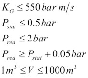
For elongated vessels (2 < L/D < 5) a correction to the vent area is indicated in the NFPA standard, which is calculated in accordance with the following formula:

More details will be found in NFPA-68 (2002)
Explosion venting is the most wide spread and cost effective deflagration mitigation technique. Design of explosion vents may be based on the vent sizing correlations or application of the computational fluid dynamics.
In general, the vent sizing formulas of NFPA 68 standard [1] and its European version EN 14994 [2] are not applicable to hydrogen because of its high K_{\mathrm G} index. Indeed, the vent sizing area formulas adopted by NFPA and EN standards are only applicable for a value of K_{\mathrm G} inferior or equal to 550 bar-m/sec. As shown in Figure C.1 of Annex C of the NFPA 68, the K_{\mathrm G} index of hydrogen increases with volume. For instance, the K_{\mathrm G} index of hydrogen rises from 550 bar-m/sec for a volume of 0.005 m3 to 780 bar-m/sec for a volume of 10 m3. This simply means that the NFPA 68 vent sizing approach for hydrogen-air mixtures is not applicable for volume larger than 5 L. Examples of comparison between the experimental data and the predictions by the innovative vent sizing technology [3] and NFPA 68 [1] are presented in Table 1. The predictions of the NFPA 68 were calculated using the value K_{\mathrm G}=550 bar-m/sec. Experimental configurations included sphere, cylinder and tunnel. Hydrogen concentrations were in the range 10-30% by volume. The vent sizing of tunnels was as follows: the volume of hydrogen-air mixture represents the enclosure volume and the enclosure vent area is naturally equal to double the cross sectional area of the tunnel.
Table 1. Comparison between experimental data and predictions by the vent sizing technology [3] and NFPA 68 [1].
| Vent Area, \mathrm{F} (m2) | Reduced pressure, P_\mathrm{red} | ||||||||||||||
| Test | [H2], vol.% | Shape | V, m3 | Igna | Newb | %c | NFPAd | %c | Expd | Newa | %c | NFPAc | %c | Expe | Use of NFPAe |
| K-10–45-C | 10 | Sphere | 6.85 | C | 0.2214 | 39 | 2.117 | 1232 | 0.1590 | 0.54 | 79 | 25.65 | 8457 | 0.300 | (-) |
| K-15-15-C | 15 | Sphere | 6.85 | C | 0.0753 | 326 | 0.493 | 2691 | 0.0177 | 5.34 | 46 | 1120 | 30418 | 3.670 | (-) |
| K-15-25-C | 15 | Sphere | 6.85 | C | 0.1002 | 104 | 0.524 | 969 | 0.0491 | 4.20 | 27 | 193.5 | 5764 | 3.300 | (-) |
| K-15-45-C | 15 | Sphere | 6.85 | C | 0.2378 | 50 | 0.682 | 329 | 0.1590 | 2.68 | 27 | 25.65 | 1121 | 2.100 | (-) |
| K-20-15-C | 20 | Sphere | 6.85 | C | 0.0536 | 203 | 0.410 | 2223 | 0.0177 | 6.14 | 22 | 1120 | 22067 | 5.030 | (-) |
| K-20-25-C | 20 | Sphere | 6.85 | C | 0.0819 | 67 | 0.435 | 787 | 0.0491 | 5.13 | 13 | 193.6 | 4155 | 4.550 | (-) |
| K-20-45-C | 20 | Sphere | 6.85 | C | 0.1643 | 3 | 0.491 | 209 | 0.1590 | 3.74 | 1 | 25.65 | 593 | 3.700 | (-) |
| P-1-C | 29.6 | Cyl | 0.95 | C | 0.2132 | 7 | 0.244 | 22 | 0.2000 | 1.35 | 8 | 1.753 | 40 | 1.250 | (-) |
| P-2-C | 29.6 | Cyl | 0.95 | C | 0.4176 | 39 | 0.49 | 63 | 0.3000 | 0.74 | 85 | 0.929 | 132 | 0.400 | (-) |
| SRI-30-F | 30 | Tunnel | 37.4 | F | 11.95 | 61.5 | 2.628 | -65 | 7.48 | 1.73 | 33 | 0.2159 | -83 | 1.300 | (-) |
| SRI-20-F | 20 | Tunnel | 37.4 | F | 11.82 | 58 | 5.6545 | -25 | 7.48 | 0.78 | 122 | 0.2159 | -38 | 0.280 | (-) |
| SRI-15-F | 15 | Tunnel | 37.4 | F | 7.55 | 1 | 7.210 | -4 | 7.48 | 0.23 | 0 | 0.2159 | -6 | 0.220 | (-) |
a C - Central ignition; F - floor ignition.
b New - Innovative vent sizing technology.
c % - Deviation of prediction from corresponding experimental value, calculated by the formula: 100 \times (A_{\mathrm{pred}} - A_{\mathrm{exp}}.)/A_{\mathrm{exp}}, where A is the reduced pressure or the vent area.
d NFPA - NFPA 68 vent sizing.
e Exp - Experimental data.
f Use of NFPA - Applicability of NFPA 68 equations. (-) in the last column refers to experimental conditions outside the specified range of applicability of the NFPA 68 equations.
From Table 1, it can be seen that the vent sizing technology predicts reasonably well both vent area and reduced pressure for different conditions whereas the predictions of NFPA 68 are shown to be significantly overestimating or even underestimating experiments.
The procedure for calculating the vent area in an empty enclosure or enclosure with insignificant influence of obstacles is as follows:
{S_u}_{\mathrm{i}}={S_u}_{\mathrm{0}} = \left(\frac{\displaystyle T}{\displaystyle 298}\right)^{1.7}
\frac{ \displaystyle \mathrm{Br}_t \sqrt[3]{36\pi_\mathrm{0}} V^{2/3}}{\displaystyle {c_\mathrm{u}}_{\mathrm{i}}\sqrt{E_{\mathrm{i}/\gamma_\mathrm{u}}}} = \frac{A\displaystyle \left(1+\pi_{\mathrm{\displaystyle}}\right)^{0.4} \left[1 + 0.5\left(\frac{A}{V^{2/3}} \frac{{c_\mathrm{u}}_{\mathrm{i}}}{{S_u}_{\mathrm{i}}(E_{\mathrm{i}} - 1)}\right)^{0.8}\right]^{0.4}}{\displaystyle \alpha \left(1 + 2 V^{0.94}\right)^{0.4}{S_u}_{\mathrm{i}}\left(E_\mathrm{i}-1\right)}
| A | vent area of an explosion venting device, in m2; | |
| \mathrm{Br}_t | turbulent Bradley number; | |
| {c_\mathrm{u}}_{\mathrm{i}} | speed of sound at initial conditions (m/s); {c_\mathrm{u}}_{\mathrm{i}}=(\gamma_{\mathrm{u}}{c_\mathrm{u}}_{\mathrm{i}}\mathrm{R}{T_\mathrm{u}}_{\mathrm{i}}/\mathrm{{M_u}_i})^{0.5}; | |
| {E_\mathrm{i}} | expansion ratio of combustion products, {E_\mathrm{i}}={\mathrm{{M_u}_i}T_\mathrm{b}}_{\mathrm{i}}/{\mathrm{{M_b}_i}T_\mathrm{u}}_{\mathrm{i}}; | |
| \mathrm{M} | molecular mass, in kg/mol; | |
| p_{\mathrm{i}} | initial absolute pressure, in bar abs.; | |
| p_{\mathrm{red}} | reduced overpressure, in bar gauge; | |
| p_{\mathrm{stat}} | static activation pressure, in bar gauge; | |
| R | universal gas constant, R = 8.31 J/K/mol; | |
| {S_u}_{\mathrm{i}} | burning velocity at initial conditions, in m/s; | |
| V | enclosure volume, in m3; | |
| \gamma_{\mathrm{u}} | specific heats ratio for unburned mixture; | |
| \pi_{\mathrm{red}} | dimensionless maximum explosion overpressure (reduced pressure), \pi_{\mathrm{red}}=$p_{\mathrm{red}}/$p_{\mathrm{i}}; | |
| \pi_{\mathrm{V}} | dimensionless static activation pressure, \pi_{\mathrm{V}}=\left(p_{\mathrm{stat}}+p_{\mathrm{i}}\right)/p_{\mathrm{i}}; | |
| \pi | = 3.14; |
The correlations have been calibrated up to date against experimental data for hydrogen-air deflagrations for the following range of conditions:
Reference & sources
In the design of a venting system it is necessary to consider the hazards that can arise from the flame and hot combustion products that would be discharged from the vent. They should be discharged into a safe area, which is away from where any personnel may be present and so it does not cause any damage to surrounding equipment. This can be particularly a problem for vented equipment located inside a building. One way of overcoming the problem is by attaching ducting to the vent so the discharge can be directed to a safe area, preferably outside the building.
The downside on the use of vent ducting is that it reduces the efficiency of the venting. The ducting will increase the flow resistance and there is the possibility of a secondary explosion of any unburnt gas initially discharged into the duct. The net effect is to reduce the flow through the vent and this lead to an increase in the reduced explosion pressure. To minimise the reduction in vent efficiency the ducting should be kept as short as possible, with no bends or large radius bends and have a cross-sectional area at least as great as the vent itself.
Meeting the above guidelines is not always practicable and even when they are met it may still be necessary to increase the size of the vent to compensate for the reduced venting efficiency. Guidance on estimating the required increase in vent size is limited. The proposed European standard on the gas explosion venting and NFPA 68, on which the European standard is based, give formula for estimating the increase in the reduced explosion pressure for ducts with lengths of less than 3 m and for ducts with lengths between 3 m and 6 m. For longer duct lengths it will be necessary to determine the effect of the duct by appropriate testing of the actual duct configuration. In the NFPA-68 2002 version, there seems to be an error in the duct length formula as the duct length to be entered in the formula is not an absolute length but the ratio of length to duct diameter. This will be corrected in NFPA-68 2006 edition.
|
Reference & sources [NFPA 68, 2002] Guide for Venting of Deflagrations, National Fire Protection Association, NFPA, 1 Batterymarch Park, Quincy, Massachusetts, USA 02169-7471 [Bartknecht, 1993] Wolfgang Bartknecht, Explosionsschutz – Grundlagen und Anwendung, Springer Verlag, ISBN 3-540-55464-5 [prEN14994, 2004] Gas Explosion Venting Protective Systems [draft version] [Molkov, 1999] Molkov V.V., (1999). Explosion safety engineering: NFPA 68 and improved vent sizing technology, Proceedings of Interflam’99, 8th International Fire Science Conference, Edinburgh Conference Centre, Scotland, UK, 29th June-1st July 1999, pp.1129-1134. [Molkov, 2003] Molkov V.V., Grigorash A.V., Eber R.M., Guidelines for venting of deflagrations in enclosures with inertial vent covers. FireSERT, University of Ulster, 2003, 41 p. [Grigorash, 2004] Grigorash A., Eber R., Molkov V., Theoretical Model Of Vented Gaseous Deflagrations In Enclosures With Inertial Vent Covers, Proceedings of the 4th International Seminar on Fire and Explosion Hazards, 8-12 September 2003, Londonderry, pp.445-456, 2004. [Dorofeev, 1995] Dorofeev, S. B., Bezmelnitsin, A. V., and Sidorov, V. P., 1995, Transition to detonation in vented hydrogen-air explosions. Comb. Flame, 103, 243-246. [Pfortner, 1984] Pfortner, H., Schneider, H., Final Report for Interatom GmbH, Bergish Gladbach, Germany, October 1984, Fraunhofer ICT Internal Report. [Sherman, 1989] Sherman, M.P., Tieszen, S.R. and Benedick, W.B, FLAME Facility, The Effect of Obstacles and Transverse Venting on Flame Acceleration and Transition to Detonation for Hydrogen-Air Mixtures at Large Scale, Sandia National Laboratories, Albuquerque, NM 87185, USA, NUREG/CR-5275, SAND85-1264, R3, April 1989. [Hansen, 2005] Hansen, O.R., Renoult, J., Sherman, M.P., and Tieszen, S.R. 2005, Validation of FLACS-Hydrogen CFD Consequence Prediction Model Against Large Scale H2 Explosion Experiments in the FLAME Facility, Proceedings of International Conference on Hydrogen Safety, Pisa, Italy, September 2005. |
A number of active mitigation methods are applied in the industry to limit the consequences of accidental fires and explosions. In the following some of these methods will be described, with particular focus on their potential benefit with regard to protection against hydrogen fire and explosion scenarios. Systems using water will be discussed separately in the next section. The concept of constant inerting is also discussed, even if this cannot be considered to be an active method. The approach is however closely related to methods like rapid pre-ignition inerting or suppression. The method is also discussed elsewhere in this report, and only a brief description will be given here.
The typical approach is to dilute the atmosphere with sufficient amount of inert gas to prevent ignition and combustion. In situations where human activity is not required, one may also replace all the air by inert gas. The inert gas will typically be N2, CO2, or special mixtures to allow human breathing but no combustion (of hydrocarbon gas at room temperature) like InergenTM (mainly Ar and N2, some CO2), ArgoniteTM (Ar, N2) or similar. The approach is typically applied for situations where the risk from accidental explosions or fire would be unacceptably high, examples are:
Challenges with such systems are that they would require proper control systems to maintain the intended dilution level. Good routines and safety systems may be required to limit the hazard to personnel, either from volumes 100% filled with inert gas, but also possible malfunction of people-safe inert gas dilution systems.
Since flammability limits are much wider and dilution levels to obtain inert atmosphere are much higher for hydrogen compared to natural gas, gas dilution to levels where humans can breath but flames not propagate is more challenging when handling hydrogen. In Table 1-4 a comparison of inert levels between natural gas and hydrogen is shown for some relevant inert gases. None of the inert gases most frequently applied for hydrocarbon gas allowing presence of people will be safe for hydrogen. Halons would be more efficient, however, the Montreal protocol with the ban on halons due to the ozone depletion effect removes this option. HFC-gases like e.g. HFC-236fa can be an option. But due to greenhouse gas effects (high Global Warming Potential) these agents are banned for fire protection use in some countries, and subject to prohibitive environmental tax in others. Since HFC-236fa has shown better performance than HFC-227ea, and will be safe for people at higher concentrations, this gas could give a certain protection against hydrogen ignition and flame propagation. The solution is questionable, as ignition should still be expected for H2 concentrations in the range 10-20%. If inerting fails, the HFC-gases may in certain circumstances decompose or take part in combustion, enhancing pressure build-up and the gases developed during combustion are toxic. It should be noticed that the values shown in Table 1-4 are for normal pressure and temperatures, and that higher inerting levels will be required e.g. for elevated temperatures [see www.safekinex.org].
Butane (C4H10) has also been added to Table 1-4 as another creative approach would be to add sufficient amount of other flammables so that the total mixture becomes too fuel rich to burn. It is expected that 8.5% butane (UFL) mixed in the air could prevent any mixture with hydrogen at ambient temperature and pressure to become flammable. Courage is however required to apply this approach as the mixture will become flammable again once diluted with air. One should then consider the possible benefits achieved from reduced reactivity due to butane dilution of hydrogen versus the increased amount of flammable substance due to the added butane.
As a conclusion, good solutions for the protection of rooms with presence of people have not been identified. For rooms or situations with no presence of people, full inerting, for instance with nitrogen, can be applied. For industrial process flows containing pure hydrogen, purging with inert gas could also be performed prior to shut-down or start-up to avoid explosions.
Fig 1 14: These plots show necessary inerting level (left) for hydrogen-air with added inert gases N2, H2O or CO2, as well as the assumed impact on laminar burning velocity (right). Relations shown are those used in the CFD-tool FLACS, and are based on [Zabetakis, 1965].
When the probability for accidental leaks is low, or there is a need for presence of people, it may not be practical to keep an inert or partially inert atmosphere constantly. Another alternative then will be to activate inert gas dilution on leak detection prior to ignition. Depending on scenario, the optimal choice of system will vary.
There will be some challenges when applying pre-ignition inert gas dilution. One will be to detect the problem and activate the system before dangerous pockets of flammable gas have built up. Personnel safety is another issue. The system must not be activated before people are safe. Further, the distribution of inert gas must be as even as possible or give better protection where the flammables are found. If CO2 is injected in a dense gas layer near the floor and the leaked hydrogen creates a flammable cloud near the ceiling, the protection is limited. On the other hand, one should also be aware that the turbulence created when injecting inert gas can make an explosion more severe if it gets ignited. A further issue to consider is a safe handling of the overpressure from injection systems with outflow of potentially explosive mixtures.
In the powder handling industry dust explosions can be a severe hazard. In many situations explosion suppression is used to quench flames, either inside a vessel or in the pipe connection between vessels to prevent escalation into further vessels. An alternative to suppression (chemical isolation) in the pipes between vessels will be explosion isolation by fast acting valves closing the pipe mechanically. More information on suppression can be found in [Moore, 1996].
To apply similar methods for hydrogen flames may be possible, but will be much more challenging. While turbulence from a suppression system alone may be sufficient to quench dust flames, the same turbulence will likely accelerate hydrogen flames. To apply suppression at hydrogen flame detection inside a room or vessel will likely make things worse, as the turbulence will strongly enhance the flame spread and no quenching can be expected. Further challenges are the short time window to detect and evenly distribute agent, the influence of real geometries that may prevent an even mixing of inert, and also the evaporation time for e.g. HFC-gases (these are normally stored as a liquid). In work towards protection of transformers, room suppression against hydrogen flames was tested [Hansen, 2002] with limited success.
The chemical or mechanical isolation of hydrogen flames burning from one vessel towards the next should be a more realistic task. Challenges will still be to detect and activate the suppression system or isolating closing valve fast enough. With fast deflagration or detonation mode flame propagation, the flame may propagate 10-20 m in 10 ms. Success with such a concept therefore depends on early detection (before flame is entering the pipe to be isolated) and rapid activation of measure. For chemical isolation (suppression) one must ensure that enough inert gas is injected for a sufficiently long period. One must be prepared that the flame may have a delayed entrance to the pipe after detection, so that the suppression system must release enough suppressant to inert a sonic flow through the pipe at least until the flame has reached the barrier. Other issues to consider is to what extent a hydrogen detonation wave will manage to propagate through a chemical barrier in its early phases, and further to what extent a plug of hot reaction products after the chemical barrier can re-ignite gases in the second vessel. Mechanical isolation seems safer if this can be done fast enough. Challenge here will be to dimension the system to withstand a reflected detonation wave.
No calculation tool has the necessary functionality and models to precisely evaluate all the aspects discussed. The physics is complex, but a range of CFD-tools can still be useful. The GexCon FLACS tool can be used to evaluate the transient distribution of inert gas, either from a suppression or inerting system. Further the influence of inert gas dilution on explosions and the effect of fast acting valves can be predicted.
Water is extensively used for fire and explosion protection. It has a high heat capacity (per mass) and heat of evaporation, water is easily available, safe and friendly to the environment, and can be applied both as liquid particles (efficient distribution) and vapor. Examples of applications are
Fine aerosol droplets [< 10 micron]: These are difficult to generate and distribute mechanically in large quantities. This can either be done when large droplets (0.5-1 mm) break up in the explosion wind ahead of deflagration flames. Another alternative for confined situations will be by flashing of superheated water. For explosion protection the water mist must be of this size class to have a beneficial effect on the flame. Larger droplets will not manage to evaporate in the reaction zone of the flame. Due to their size, these small aerosol droplets will follow the flow. If significant flow velocities are present in the accident scenario, they may be transported away by wind or convection flow from fire and have no beneficial effect.
Explosion tests with such a fine aerosol system from Micromist Ltd. [Hansen 2002b, 2002c] have shown that stoichiometric propane can be made inert, while a significant pressure reduction 50-70% was achieved with hydrogen using 4 litre/m3 prior to ignition in a 50m3 vessel with low congestion and relative low vent area. Compared to natural gas, tests seemed to indicate that of the order 3 times more water mist must be applied for hydrogen to achieve similar relative pressure reduction.
Fine mist [30-200 micron]: These can be generated by commercial mist/fog nozzles. Due to a better ability to penetrate the flow, but limited size giving fast evaporation, they may be useful for fire mitigation. For explosion protection this droplet size will have a limited or even negative effect, as the turbulence from their distribution will accelerate flames, but the evaporation time scales are too large for deflagration flames. GexCon has performed hydrocarbon explosion tests using fog nozzles for mitigation. This resulted in increase of pressure instead of a decrease. The reasons for this were strong initial turbulence from sprays and combined with limited mitigation due to too large droplet size for efficient evaporation (but too small droplets to achieve droplet break-up).
Droplets from sprinklers [400-1000 micron]: These can be generated from normal sprinklers at 3-7 bar water pressure. These droplets may have a positive effect on large-scale fires, but may be less efficient for smaller fires compared to the previous category. For unconfined and partially confined explosions, these droplets may be very efficient. Due to their size they are not so much influenced by strong natural ventilation or buoyant convection flow from a fire. When explosion starts, the sprays will initially accelerate flames. Very soon these droplets are broken up into very fine mist particles due to the forces from the expansion flow ahead of the flame. The fine mist will be efficient against explosions as the flame reaction zone is diluted with fine aerosol particles. The efficiency of such a system increases with scale, with amount of water, with equipment congestion and with decreased confinement. For natural gas hazards on offshore installations, typical application rates are 10-25 litre/sqm/min depending on area to be protected. For explosion protection, 10 litre/sqm/min is not necessarily sufficient if the confinement is significant. For hydrogen the beneficial effect may be even harder to achieve, this will be discussed in the next section.
Advantica [Catlin, 1993, Selby, 1998, Al-Hassan, 1998], and GexCon [van Wingerden, 1997, 1998 and 2000] have performed numerous tests with sprinkler systems to study explosion mitigation for natural gas. This has shown a very beneficial effect at large-scale when confinement is low. With low congestion and high confinement, less good results are seen, and in some situations the use of water deluge may make the explosion consequences significantly more severe..
Despite a significant research effort on water mitigation of natural gas, limited work has been done on hydrogen. The effect of inert water vapor on hydrogen flames is one exception. In the following it will be discussed to what extent water can be used to improve hydrogen safety.
For a situation where accidental releases of hydrogen can take place, a sprinkler system with water could enhance mixing and avoid stratification effects. If the total amount of hydrogen that can leak is small compared to room volume, this can be a good idea as very reactive flammable clouds may be avoided. For larger releases, this may strongly increase the hazard, as a large homogeneous cloud at dangerous concentration may form. A forced ventilation or fan system could have the same effect.
If there is a wish to add heat to released gas to enhance buoyancy of the cold plume, water curtains directly downwind or around a cryogenic hydrogen spill dike could be to some help. It should be confirmed that no ignition hazard is introduced due to static electricity. Static electricity from nozzle systems does not seem to be a problem for natural gas clouds exposed to deluge, however, minimum ignition energy for hydrogen is 10 times lower than for propane.
Against fire it is assumed that water can be applied to cool equipment exposed to radiation or flame impact, to cool the flames, and possibly also to set up a radiation shield where needed. Quite a lot of water vapor will normally be needed for extinction of hydrogen flames. Turbulent jet flames may lift-off with increased water vapor level. To quench hydrogen flames may be very difficult, and will seldom be a beneficial result in relatively confined situations as an uncontrolled leak and potential explosion may follow.
For explosion mitigation an aerosol water system based on flashing of substantial amounts of superheated water (4 litre/m3 water at 180şC/10 bar) has been shown to reduce hydrogen explosion pressures significantly. More than a factor of two reduction of overpressure was achieved at 15-20% H2 concentrations [Hansen, 2002b]. More water is expected to improve the effect further, but the release of hot water may lead to a significant temperature increase and a certain overpressure at activation. Best effect will be seen if injected short time before ignition. The suppression of the hydrogen flames inside a room with such a system will likely not work, due to problems with activation time and turbulence from release. In special situations a system could still work, for instance being released in compartments where the flames have not reached yet. Steam (water vapor) would be expected to have a similar (or better) effect, but the distribution of significant amounts of steam will take time and build up pressure. Water sprinkler systems activated at release prior to ignition could be expected to have a mitigation effect on hydrogen explosions in certain situations. Significant more water than applied for natural gas would be needed. Potential problems include the possibility that turbulence from sprays may quickly accelerate the flames into DDT and detonation, and then the water sprinkler will not be expected to have a mitigating effect any more. The much lower minimum ignition energy for hydrogen compared to natural gas may also increase the likelihood for ignition from static electricity in connection to the water sprinkler systems.
The conclusion will be that potential benefits from using water-based protection systems within hydrogen safety may exist. For protection against fire effects, traditional methods should be applicable. There are few good solutions at the moment to handle explosions, more work will be needed to identify and validate good systems. Further development and testing of the fine aerosol technology from superheated water should be performed and the potential benefits and problems for sprinkler systems should be investigated.
No calculation tool has the necessary functionality and models to precisely evaluate all the aspects discussed. Several CFD-tools can be used to study the effect of deluge on dispersion. Some CFD-tools have models for the effect of deluge on deflagration flames, these are mainly valid for natural gas. The GexCon FLACS tool has modified guidelines for hydrogen and deluge, but experimental validation is limited.
|
Reference & sources [Isaksson, 1997] Isaksson, S., Simonson, M. and Holmstedt, G., Sveriges Provnings- og Forskningsinstitutt, SP report 1997-10 [SFT, 2001] Norwegian Pollution Control Authorities (SFT), SFT report 1754-2001 [Zabetakis, 1965] Zabetakis, M.G. “Flammability characteristics of combustible gases and vapours”, Bureau of Mines, Bulletin 627, Washington 1965 [Hansen, 2002] Hansen, O.R., Wilkins, B.A. and Wiik, A.,”Suppression of secondary explosions in transformer rooms”, J.Phys.IV France 12 (2002) [Hansen, 2002b] Hansen, O.R., Wilkins, B.A. and Eckhoff, K. "Explosion protection in transformer rooms” ESMG symposium proceedings, Nurnberg,8th -10th October 2002. [Hansen, 2002c] Hansen, O.R., Wilkins, B.A., Eckhoff, K., O’Connell, M. and Holen, J.K., Mitigation and prevention of hydrocarbon explosions by micromist water inerting, Conference proceedings Major Hazards Offshore, 2003, London, UK, ERA report 2003-548, ISBN 0 7008 0776 4 [Moore, 1996] Moore, P.E. “Suppression of Maize Dust Explosions” Industrial Dust Explosions, Symposium Pittsburg, Pennsylvania, June 1996. [Jones, 2006] Jones, S.J., Averill, A.F., Ingram, J.M., Holborn, P.G., Battersby, P., Nolan, P.F., Kempsell, I.D. and Wakem, M.J., Mitigation of Hydrogen-Air explosion mixtures using fine water mist sprays, Hazards XIX Conference proceedings, Manchester, UK, 27-30 March 2006. [Al-Hassan, 1998] Al-Hassan, T. Johnson, D.M. “Gas explosions in large scale offshore module geometries: Overpressures, mitigation and repeatability, presented at OMAE-98, Lisbon, Portugal, 1998 [Selby, 1998] Selby, C., Burgan, B. “Blast and fire engineering for topside structures, Phase 2, Final summary report”, Steel Construction Institute, UK, Publication number 253, 1998 [van Wingerden, 1997] van Wingerden, K. and Linga, H. “New aspects of the effect of water spray on gas explosions in offshore rigs”, Conference on Fire and Blast Engineering: Offshore Installations, ERA-report 97-0994, London 1997 [van Wingerden, 1998] van Wingerden, K., Hansen, O.R. and Lemousy, T. “Effect of deluge on explosions, FLACS simulations compared to full scale experiments”, 7th Annual Conference on Offshore Installations, ERA-report No 98-0958, ISBN 0-7008-0679-2, London 1998 [van Wingerden, 2000] van Wingerden, K “Mitigation of gas explosions using water deluge”, Process Safety Progress, Volume 19, Issue 3, Pages 173-178, 2000 [Catlin, 1993] Catlin, C., Gregory, C.A.J., Johnson, D.M., Walker, D.G., “Explosion mitigation in offshore modules by general area deluge”, TransIChemE, vol. 71 Part B, 1993 |
In this section various passive methods and their potential influence on the hydrogen safety will be discussed. Passive measures will include elements such as “Inherently safe design”, “Soft barriers” as well as certain protection measures that are constantly in place and thus require no maintenance. Because of the high reactivity of hydrogen, and the limited benefits expected from active measures, special consideration should be given to find the optimal passive protection methods. For gas explosions, some best practice advice can be found in [Bjerketvedt, 1997], see examples in Figure XX.
Figure XX: Some illustrations from Gas Explosion Handbook [Bjerketvedt, 1997] indicating best practice layouts for explosion exposed areas.
The main focus here should be to avoid significant flammable gas clouds. Some focus will also be on limiting overpressures if an explosion takes place. Both these goals can be achieved by minimizing the confinement (the optimal wall is no wall).
The strong positive buoyancy of hydrogen should be exploited, and one should ensure that released hydrogen finds its way upwards without meeting too much confinement. In outdoor situations, this can be ensured by proper design of ceilings and covers. Large high-momentum leaks inside a process area may still generate significant cloud sizes. If this turns out to be a problem, methods can be applied to reduce the momentum of horizontal leaks, e.g. putting up vertical walls around the likely leak locations. By reducing the momentum of the leak, it will much sooner find its way upwards. This may reduce cloud sizes (but increase likelihood of small explosions as more frequent smaller leaks may now generate flammable clouds). Such a measure should therefore not be applied without a proper risk evaluation.
Another issue in the design is that different units should be separated so that the gas cloud from one unit does not reach the next unit.
In semi-confined situations, one should further ensure that natural ventilation in combination with buoyancy effects will be as efficient as possible preventing gas cloud build-up for different wind conditions. Again focus should be on designing the ceilings so that buoyant layers of gas will find its way out of the vent openings.
For a more confined situation it will depend on the leak rate whether a low momentum release (more stratification, beneficial for large amounts released or if gas near ceiling is quickly removed) or high momentum release (more mixing, beneficial provided concentration can be held e.g. below 8%) is preferable. A casing around the leak exposed equipment can ensure a low momentum leak. Similar effects may be achieved by applying weak barriers, like curtains. This may let some of the gas through, but may reduce the size of very flammable gas clouds.
If a gas cloud is generated and ignites, presence of large vent areas will usually be an advantage to limit explosion pressures. If the vent areas are well distributed, this may reduce the flame acceleration through the geometry and the severity of the explosion. A strong feedback from external explosion into the chamber increasing the turbulence and flame speeds may also be less likely when vents are distributed. In some situations it will be an advantage that the vent panels close after an explosion to limit access to oxygen for the following fire.
The congestion level should also be made as low as possible, to limit turbulent flame speeds. In areas exposed to hydrogen leaks, the area near the ceiling should be given particular attention, as the gas is likely to collect there. It may then be a good idea to limit the equipment density near the ceiling, to avoid equipment that will accelerate flames in that region. If there are significant support beams below ceiling, these may both be an advantage as they may influence the shape of the gas cloud, but also a disadvantage accelerating flames. When designing such facilities, one should have a philosophy about this before deciding on the detailed layout.
It is not always straight-forward to choose the optimal design based on the guidelines above. Several of the considerations will depend on the frequency and consequences of various incident scenarios. If one design choice is taken, one should expect this to increase the frequency/consequence of certain incidents, and reduce the frequency/consequences for other. When evaluating these issues it is important to apply methods that take the complexity of the phenomena into consideration. If consequence tools are to be applied, this will in many situations mean that CFD-tools should be applied, as simplified guidelines will not pick up the physics.
One approach to protect sensitive equipment from explosion effects will be to design some kind of barrier between a source of explosion and a sensitive target. This is sometimes done in connection to the handling of explosives, and also for situations in the chemical industry to protect surroundings from high pressure tanks with potential unstable chemicals that may explode [Herrmann, 2005]. It is also sometimes used to deflect flames in connection to explosion venting, either to prevent people from being killed by fast vented flames, or to protect buildings directly outside an explosion vent. Like for many other mitigation measures the design and optimization of a protection wall is not straight forward. Important design questions are:
Where to locate the wall? The wall can either be located close to the source to absorb the energy from the explosion or venting, or it can be located close to the target to shield the target from pressure waves. For a deflagration it is in general difficult to identify the exact position of the explosion source, and it will usually not be practical or cost-efficient to use this as a mitigation measure. One exception is when there is a vent opening, in this case one may know where the energy comes from, and it will be possible to design a protection wall. The alternative approach will be to design a protection wall in front of the target. In order to have a good effect, one will have to study the detailed interaction between blast waves and the wall & building complex and optimize size & position based on such a study. It can be a challenging task to design a good protecting wall, and in most cases it will be better to spend the same resources strengthening the target building.
How large should the wall be? This can be a difficult question to answer as it will depend on several parameters, including position and volume of source explosion relative to object to be protected. For a geographically well defined detonation or vessel burst situation that can be considered as a point source, an optimization of wall design may be possible, for a less well defined source a significant conservatism will normally have to be included.
How strong must the wall be? If the wall is located near the source, it has to be stronger than if it is located close to the target. In both cases, it should not generate projectiles as a result of the blast loads. If the incident is statistically rare, it may be acceptable that the wall is damaged by the incident.
By studying such approaches with protection walls against blast waves, one will normally realize that the effect of shielding walls is usually limited. Parameter studies may also show that it is fully possible to make the blast loads worse depending on location and size of the shielding wall. This can be partly because the pressure will go around the wall on all sides (above and to the sides), and these pressure waves will be deflected and may again meet behind the wall. In the planes where these deflected waves will meet, one may experience higher pressure loads than for the reference case with no walls. Another issue is that the pressure waves coming from a different angle compared to the case with no protection wall may be more dangerous giving a stronger reflected pressure.
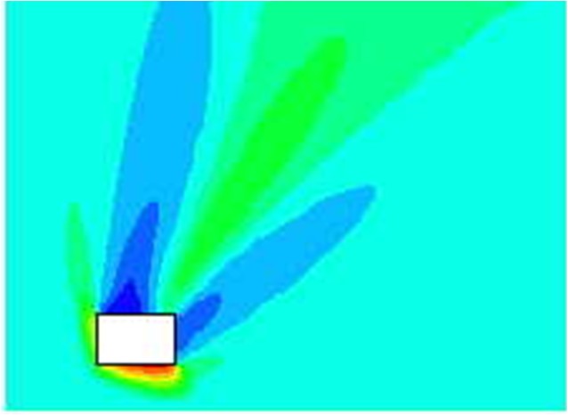
In the following an example of the testing and modeling of protection walls will be given.
Forecast of blast wave propagation and impact force which is applied to the protective wall
In case if explosion accident occurs, it is necessary to have some measures in order to minimize the disaster of material and personnel on the surrounding area. For this purpose, the design conditions of protective wall was investigated in order to obtain more efficient reduction of blast wave by means of calculating the blast wave propagation using compressible fluid simulation for the postulated explosion accident. The benefit of protective wall installation was examined based upon the numerical simulations of blast wave propagation by the BAAL which is open source code of Los Alamos National Laboratory. Fig. 1 shows a reduction effect of explosion overpressure by various protective walls.
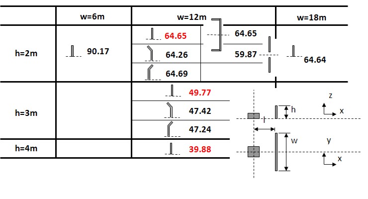
Fig.1 Comparison of reduction effect of explosion overpressure of various protective walls
The value in Fig. 1 represents a reduction effect of explosion overpressure, and this is calculated as per cent value of explosion of overpressure to that without protective wall at a distance of 10 meter downstream from the protective wall. Based upon the result which is shown in Fig. 1, it becomes clear from this simulation that protective wall should have certain width at least 12 meter, and the reduction effect of explosion overpressure greatly depends on the height of protective wall and does not depend on its configuration.
Explosion experiments were carried out in order to evaluate the damage of surrounding reinforced concrete (RC) structures and to enable a structural design of it by numerical simulations. (See Fig.2)

For the experiment, pre-mixed 37 m3 of 30% hydrogen with air was detonated with the RC test pieces located at 5 meter from explosion center, and response and damage of test pieces were observed. The number of RC test pieces is 22 with a different height, thickness, bar arrangement and steel ratio. Table 1 shows the result of experiments with a broad range of conditions from elastic stage to breaking.
Table 1: Experimental results on RC structure damages caused by hydrogen explosions
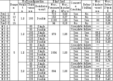
The explosion results show that response of the structures has a significant time lag behind the blast wave propagation. And because a trace of crack shows an evidence of higher order deformation mode, the damage of RC structure is caused by a vibrational phenomenon which is dependent on the natural frequency of it. (See Fig.3)
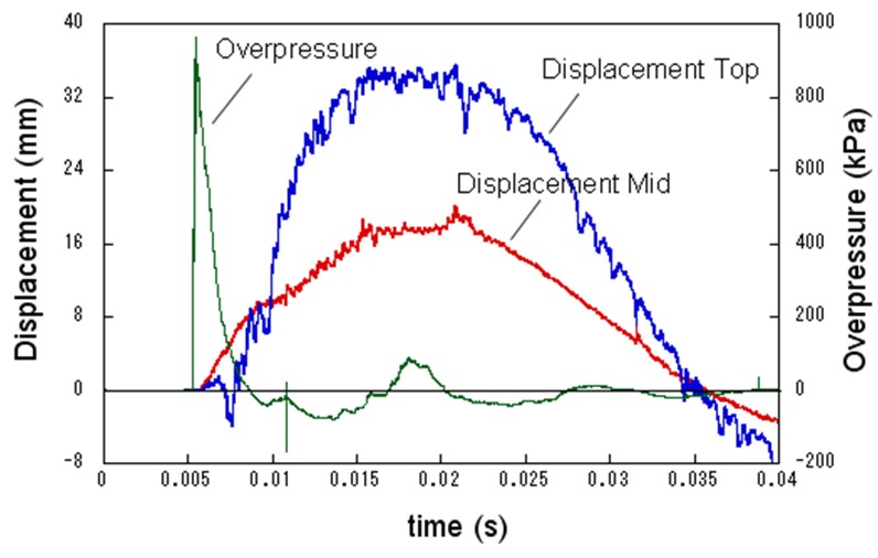
Fig.3 Typical displacement response
Result obtained from the coupling of a blast wave analysis by AUTODYN and a response analysis by FINAL which is analysis software for a structure developed by Obayashi Corporation agrees well with the experimental result. (See Fig.4) Therefore, this phenomenon is found to be simulated with above-mentioned software.
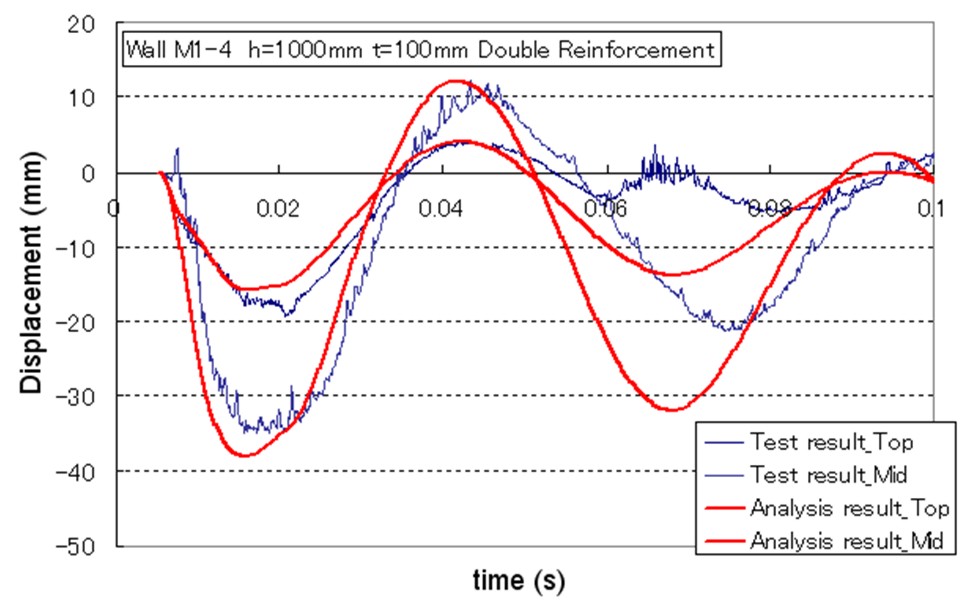
Fig.4 Comparison of simulation and experiment concerning displacement response
The concept of soft barriers for explosion mitigation was discussed in [Tam, 2000]. A soft barrier could be a polyethylene sheet preventing gas to enter into regions where explosions could become more severe due to pressure piling or reflections. Another soft barrier could be to put a cover around a congested pipe bundle. A gas explosion will accelerate much less going past one large “cylinder” compared to a pipe bundle. A third example would be to fill the upper half of a room with balloons. A released gas will only be able to fill half of the volume. If this explodes, the overpressure will manage to expand as the balloons get compressed. If the balloons also fill space between beams (repeated beams would normally accelerate the flames), the effect from such measures can be very significant.
The possibilities with such soft barriers are numerous. Another example could be a pattern of regular vertical curtains. Workers could easily walk through the curtains, so the limitations to the normal work operations could be limited. A high momentum jet release on the other hand would soon lose its momentum and move upwards due to buoyancy. The curtains would also limit the mixing of gas. The flammable cloud size would then be limited (a small rich region, other lean regions, and some regions with no gas at all). Once the explosion would start, the soft barriers will act as weak vent panels in all directions.
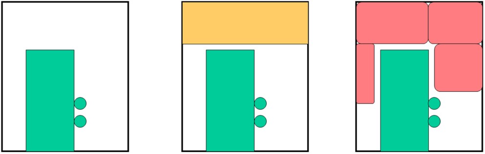
Flame quenching and quenching diameter Cold walls quench the flame over a fairly long distance. The observation led Sir Humphrey Davy to the invention of the miners safety lamp in 1815 and has been used ever since in the construction of various explosion proof equipment including flame arrestors used to protect storage, distribution and chemical processing facilities containing flammable gases from fire and explosions. Typically the arrestors are composed of metal plates with orifices, wire mesh screens, porous sintered metal elements, etc.
The flame quenching by walls can be due to cooling and chemical effects in particular destruction of radical chain carriers. By testing different mixtures of the same composition diluted in different proportions by argon and helium which changes the ratio of diffusion coefficients and thermal conductivities of the mixtures without affecting the chemistry it was proven that heat transfer is by far the dominating mechanism. Then simple physical considerations lead to the conclusion that the quenching distance dq should be proportional to the flame thickness that in turn is related to the laminar burning velocity, SL
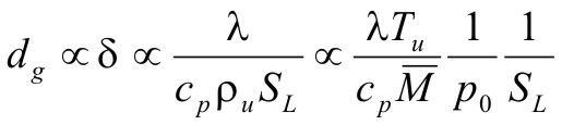 (1)
(1)where, λ is the thermal conductivity, cP is the specific heat at constant pressure, ρ is the density, T is the temperature and  is the average molecular weight, and the subscript u denotes the unburned state. The above equation is a surprisingly exact one, and only the additional, typically weak, pressure dependence of the SL introduces some discrepancies. It is interesting to note that only about 22% of the heat generated by the flame per unit surface must be removed in order to quench the flame.
In some methods the flame is quenched using a circular tube in which case, one often speaks of the quenching diameter D0. In other methods it is convenient to quench the flame by a tube of slot like cross section, in which case one speaks of the quenching distance referring to the width of the slot.
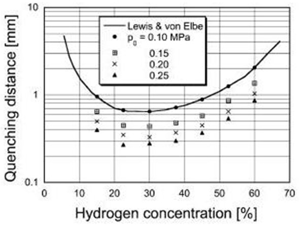
In Fig .1 quenching distances are plotted as function of hydrogen concentration in air at 300 K for various initial pressures after Yang et al. [Yang, 2003]. In the figure also data of Lewis and Elbe [Lewis, 1987] are shown for comparison. The quenching distance has its minimum at about 30% vol. of hydrogen i.e. practically at stoichiometry. Other geometries provide different quenching distances. The geometrical factor could be calculated from the requirement that the heat loss rate at which flame is quenched is a constant independent of tube geometry. The geometrical quenching factors were studied by Berlad and Potter [Berlad, 1955]. The following relations were proposed for D0, quenching distance D1 and quenching by a rectangular slit D2 with the shorter side Dr and longer side b.
 (2)
(2)Other geometries were also analysed. Although the predicted and observed values agreed well, systematic deviations were observed, which required empirical correction factors (typically of the order of 10%). The length of the quenching hole is unimportant, both orifices in foils and thick plated provide the same results. Several investigators looked for an effect on quenching distance of the nature of the wall and found none, even when the walls were coated with special chain breaking salts of various efficiencies.
Maximum experimental safe gap (MESG)
Forced flow conditions, like the ones occurring during explosion, make a difference. Thus, the following problem is of importance. A mixture is ignited, or explodes in a closed vessel. The same mixture surrounds the vessel. What is the maximum safe width of a slit in the vessel (sometimes referred to as the “maximum experimental safety gap” MESG) for the flame to spread outside. Propagation of the flame under such condition is a much more complex process due to the domination of non-stationary and gas-dynamic phenomena. A landmark analysis of the problem was provided by Phillips [Phillips, 1963]. Discussion of the problem is beyond the scope of this note and as an indication of the orders of magnitude in Table 1 we give the width of the “explosions proof” slits and D1 for several mixtures after Chomiak [Chomiak, 1990]. It is interesting to note that MESG is by a factor of two larger than quenching distance at explosion pressures for most fuels, except acetylene where it is less than half. This aspect of flame quenching is poorly understood and requires more work. These values relate to stationary flame. If the gas flow is in the direction of flame propagation, a smaller gap is needed to quench the flame, and conversely. If the gas velocity is high enough, a condition can occur in which a flame propagating against the flow is stabilized at a constriction and causes local overheating.
Table 1: Comparison of MESG and quenching distances for several mixtures [Chomiak, 1990]
Deflagration Flame Arresters
A flame arrester, or flame trap, is a device used to prevent the passage of a flame along a pipe or duct. A flame arrester is generally an assembly of narrow passages through which gas or vapour can flow, but which are too small to allow the passage of flame. Flame arresters are generally distinguished as end-of-line or in-line arresters. There are three types of arresters:
The operation of type 1 arresters is generally treated in terms of the mechanism of quenching and heat loss. Desirable properties of a flame arrester are high free cross-sectional area available for flow, low resistance to flow and freedom from blockage; a high capacity to absorb the heat of the flame, and the ability to withstand mechanical shock, including explosion. The design of flame arrester depends on the combustion properties of the flammable mixture and on the function and location of the arrester. The size of the aperture through the arrester is determined by the quenching distance of the flammable mixture. The diameter of the aperture of an arrester should be smaller than the quenching diameter by at least 50%. The performance of an arrester is affected by the temperature. The quenching distance increases as the temperature increases. It is approx. inversely proportional to the square root of the absolute temperature.
Hydraulic, or liquid seal, arresters contain a liquid, usually water, which serves to break up the gas stream into bubbles and so prevents passage of the flame.
Velocity flame stoppers are arresters used in end-of-line applications. Their function is to prevent a flame passing from downstream to the upstream side. The principle of their operation is to assure that the velocity of the upstream gas passing through the arrester is sufficiently high to prevent a flame propagating through the arrester from the downstream side. The velocity necessary to prevent flashback through apertures larger than those which would give quenching is given by the equation [Hajek and Ludwig, 1960]:
uT = 0.2015gLD
where: D – internal pipe diameter (m)
More details on flame arresters, including technology and list of manufacturers can be found in the book by Grossel [Grossel, 2002].
Several types of flame arresters have been tested for hydrogen service and found acceptable for quenching of hydrogen-air and hydrogen-methane-air mixtures. Howard et al. [Howard, 1975] conducted experiments on three types of flame arresters for quenching fuel mixtures of hydrogen and methane with air. Tests were run at pressures of 0.02 and 0.08 MPa and feed gas temperatures of ambient, 423 K, 473 K and 523 K. In these experiments only the velocity stopper was able to stop all flame propagation.
Some crimped metal ribbon flame arresters have been tested for hydrogen service and can be used. [Protego, 1993) has both deflagration and detonation flame arresters, ranging in size from 10 mm to 400 mm, approved in Germany for mixtures of hydrogen and air in all ranges of concentration. Enardo [Enardo, 2005] has also in-line flame arresters for hydrogen-air mixtures. NAO has designed and successfully tested and provided a hydraulic flame arrester for hydrogen-air applications. Rao [Rao, 1980] also provides information on a hydraulic flame arrester that was designed and used successfully for hydrogen service in a nuclear power plant.
Flame arresters are the subject of a number of codes and standards in different countries. In the UK BS 7244 – 1990 [BS, 1990] covers the testing of arresters. In the USA the Underwriters Laboratories standard UL 525-1989 [UL, 1990] deals with construction and testing. Also in the USA the American Petroleum Institute has API PB 2028.2002 standard [API, 2002]. Germany has legally backed standards on the same aspects. The International Maritime Organization (IMO) also has requirements for flame arresters [IMO, 1984]. A new CEN European standard, EN 12874 was issued in 2001 [CEN, 2001]. This is very comprehensive standard covering many aspects of flame arrester technology.
None of the deflagration arrester designs can withstand a detonation. Therefore the detonation flame arrestor was designed. Detonation arresters are devices designed to withstand and extinguish the high speed and high pressure flame front that characterizes a detonation propagating through a piping system. Therefore, a detona¬tion arrester must be able to withstand the mechanical effects of a detona-tion shock wave while quenching the flame. Some designs have a "shock absorber" in front of the flame arresting element to reduce both the high pressure shock wave and the dynamic energy and to split the flame front before it reaches the flame arrester element. Another design variation has what is called a "detonation momentum attenuator" (DMA) [Westech 1989]. Detonations occurring in piping have velocities of about 2000 m/s, or greater, and in closed process vessels and equipment can generate pressures from 20 to 100+ times the initial pressure. Detonation flame arresters are available for hydrogen as both unidirectional or bidirectional types. When installed in a vent manifold system the flame arresters on the tanks may be unidirectional or bidirectional, depending on the manufacturer's recommendations. They should preferably be installed in a vertical orientation, so that if liquid is present, the arrester will drain. If they must be installed in a horizontal orientation, they should be provided with drain connections. Most detonation arresters have crimped metal ribbon arrester elements, although expanded metal cartridges are also used. Arrester elements for detonation arresters are usually longer than for deflagration arresters. Detonation flame arresters impose higher pressure drops than deflagration flame arresters due to heat transfer requirements, they are heavier because of structural requirements, and they are typically more expensive. Instantaneous impulse pressures caused by the shock waves of overdriven detonation subject the arrestor to forces up to 34,000 kPa(g) at atmospheric initial pressure.
Volume filling of tanks with thin metal objects with large surface
The fact that surfaces will cool a flame can also be exploited in a different way. If a potentially flammable volume, like a fuel tank in a fighter plane or a racing car, is packed with small elements built up from thin metal foils, this will represent a very large surface area. The volume occupied by the metal object may still only be of the order a few percent, so the influence on the tank performance may be limited. A flame burning in this volume will then experience a very substantial heat loss, and may quench. Such methods have been applied for certain applications for hydrocarbon vapors of moderate reactivity. Since the quench distance and MESG is one order of magnitude smaller for hydrogen than for typical hydrocarbons, requirements for fineness of metal structures will be much higher since 10 times shorter distance between cells will require 1000 times more cells in 3 dimensions. It should still be possible to benefit from such a method, even if the design would allow the flames to burn, heat will be extracted from the burnt gases which could both reduce the burning velocity and terminal pressure. If the cells of the metal structure are too large, they could accelerate the flames. One example of a company manufacturing such a concept is [eXess, 2006].
|
Reference & sources [Bjerketvedt 1997] Bjerketvedt, D., Bakke J.R. and van Wingerden, K., Gas Explosion Handbook, Journal of Hazardous Materials 52 (1997) 1-150 [Tam 2000] Tam V (2000), Barrier Method: An Alternative Approach to Gas Explosion Control, FABIG Newsletter, R372, The Steel Construction Institute, UK [Herrmann, 2005] Herrmann, D.D., Developing a sound bases for the design of vented explosion barricades in chemical processes, Process Safety Progress, Volume 24, Issue 1, pp 52-58, March 2005 [Westech, 1989] Westech Industrial Ltd. 1989. Flame Arrester Seminar Notes. Westech Industrial Ltd. Calgary, Canada [Yang, 2003] S. Y. Yang, S. H. Chung, H.J. Kim. Effect of pressure on effectiveness of quenching meshes in transmitting hydrogen combustion. .Nuclear Engineering and Design, 224 (2003) pp. 199-206. For additional data see also: Hong Seong-Wan, Shin Yong-Seung, Soug Jin-Ho, Chang Soon-Heung. Performance test of quenching meshes for hydrogen control. Journal of Nuclear Science and Technology, 40 (2003) pp. 814-819. [Lewis, 1987] B. Lewis, G. von Elbe, Combustion, Flames and Explosions of Gases. (3rd edition) Academic Press, New York, 1987. [Berlad, 1955] A. L. Berlad, A. E. Potter. Fifth Symposium (International) on Combustion, Reinhold Publishing Corp. 1955, pp 728-735. [Phillips, 1963] H. Phillips. On the transmission of explosion through a gap smaller than the quenching distance. Combust. Flame, 7 (1963) pp. 129-135. [Chomiak, 1990] J. Chomiak. Combustion A Study in Theory Fact and Application. Gordon and Breach Science Publishers, New York, 1990, p. 56. [CEN, 2001] CEN EN 12874.2001. Flame Arresters – Specifications, Operational Requirements and Test Procedures. European Committee for Standardization, Brussels, Belgium [IMO, 1984] IMO (International Maritime Organization) MSC/Circ. 373. 1984. Standards for the Design, Testing and Locating of Devices to Prevent the Passage of Flame into Cargo Tanks in Oil Tankers. International Maritime Organization, London, England, UK [UL, 1990] UL 525. 1994. Standard for Flame Arresters. 6th edition. Underwriters Laboratories, Inc., Northbrook, IL. [BSI, 1990] BSI (British Standards Institution) BS 7244. 1990. Flame Arresters for General Use. British Standards Institution, London, England, UK. [API, 2002] API PB 2028. 2002. Flame Arresters in Piping Systems. 2nd ed. American Petroleum Institute, Washington, D.C [Grossel, 2002] S.S.Grossel. Deflagration and Detonation Flame Arresters. American Institute of Chemical Engineers, New York 2002 [Enardo, 2005] Enardo. Flame Arrester Technology. Technical Bulletin, 2005, www.enardo.com [Protego, 1993] Protego. Special Catalogue of Protego Flame Arrester for Hydrogen Systems. Protego Publication No. NO770993. Braunschweiger Flammenfilter GmbH, Germany, 1993 [Howard, 1975] Howard W.B., Rodenhorts C.W., Small G.E. Flame Arresters for Hydrogen Fuel-Air Mixtures. CEP Loss Prevention Manual, 9 (1975) 46-53 [Nao, 2005] NAO Inc. 2005, www.nao.com [Rao, 1980] Rao S.N., Dam A.S., Maus F.G. Detonation Flame Arrester Testing for Oyster Creek Nuclear Station. ANS/ENS Int. Conference on World Nuclear Energy, Washington, 1980 [eXess, 2006] eXess Engineering GmbH, http://www.exess.at/ |
Emergency response methods available for a hydrogen “loss of containment” incident will to some extent be similar to emergency response to loss of containment for other gaseous fuels. Active fire fighting is not as effective as for petrol or diesel, and more emphasis will thus have to be laid on extensive emergency response planning. The emergency response plan should reflect the foreseen major hazards and aim at minimize the risk to people.
General principles for emergency response planning may, in the absence of guidelines specific for hydrogen, be extracted from other areas where extensive emergency planning is seen as essential.
Guidelines for emergency response for offshore installations are given in [ISO, 2000]. A basic principle is that emergency planning should be based on systematic identification of hazards, followed by evaluation and risk management.
The initial step in emergency response planning would be the emergency response strategy, describing the general philosophy on how the organization, procedures, equipment training and other measures are supposed to work together to deal with foreseeable incidents – even in the case of failure of an emergency response measure. For a hydrogen leak the direct mitigation means could for instance be deactivation of ignition sources upon gas detection, to prevent ignition. (Ignition source control is described in Ch 5.6.6.) This measure may not be effective, possibly even leading to ignition, and warning and escape procedures as well as egress routes will thus have to be part of the strategy. Moreover, as these measures both rely on the detection and communication of a hydrogen leak, detection (See Ch 5.7.1) and communication should have a high reliability.
Communication is a key element in any emergency response plan. Effective communication will involve technical measures, organization, procedures and training adapted to each other and to the overall strategy. If communication fails, effective emergency response is not possible.
Technical communication measures could initiate automatic actions such as shut down of electrical power supply, or initiate an alarm, emergency ventilation, enabling manual (human) intervention or escape. Technical communication measures will also be needed for mobilization and communication within the emergency response organization and for mobilization of external resources. All of these measures will have to have a high reliability, and in cases where human action is intended (mobilization, intervention or escape), the recipient’s ability to receive the message and discern the essential information must also be considered.
Effective emergency response will also require an organization intended and prepared for emergency response. The lines of communication should be well known and worked in, preferably the same as for daily operation. Emergency procedures, and especially the function and use of communication equipment, should be known and tested within the organization.
Escape/evacuation of people should be part of the initial planning of any new or modified installation. Escape routes are easy to implement at the design stage, but may be rather expensive or nearly impossible to implement if thought of too late. The principle of two escape routes from all areas regularly occupied by humans is laid down in most countries building regulations and should also be applied for outdoor facilities such as refueling stations. Bearing in mind refueling stations may be placed in congested areas and close to a highly trafficked road, this may not be straight-forward to accomplish.
Liquid spill on water
Spill of liquid hydrogen on water may lead to Rapid Phase Transition (spontaneous and explosive boiling of liquid hydrogen) due to the rather favorable heat transfer conditions and a practically unlimited reservoir of heat. The phenomenon is described by several sources, e.g. by [Hightower, 2004] for liquid natural gas (LNG) on water, where the temperature difference is less than for liquid hydrogen and water.
Emergency response in such a case should include warning of boats in the area against sailing into the gas cloud. In some cases even car traffic may have to be stopped or re-directed. Warning of other people in the area, especially downwind of the release is also important, though the gas cloud may not be of such duration to expect any benefit from evacuation of people.
Liquid spill on ground
Spill of liquid hydrogen on ground can be expected to give less rapid evaporation than spill on water. The spread of liquid may be constrained, either by design of storage facilities or by natural formations. The best industry practice for storage of flammable liquids or condensed gases would be to lead liquid spills away from storage tanks (as well as temporarily stored transport tanks) by sloping ground (ditch) a collection basin, minimizing the liquid surface and thus minimizing evaporation. Hydrogen pool fires are described in Ch. 3.1.8.6. Prevention of ignition would normally require a larger safety distance than the protection of people from a pool fire. Emergency response should encompass warning of people in the area and re-routing of traffic to prevent cars from driving into the gas cloud.
Gaseous releases and dispersion of released gases are described in Ch. 3.1.1 and 3.1.2.
Guidelines for emergency response for gaseous releases can be found in offshore standards, e.g. from [ISO, 2000 and 1999]. Though hydrogen’s properties are different from those of petroleum gases, there are also similarities: Methane is buoyant in air, and methane releases are often seen as the most hazardous flammable gas releases on offshore installations because methane gas will not sink towards sea level. A number of general principles for danger limitation should be transferable to hydrogen releases:
Hydrogen gas fires are described in Ch. 3.1.8.7. An ignited gas leakage is not easy to extinguish, and the principle normally applied is to protect the surroundings as far as possible from the effects of the fire and prevent escalation. Guidelines for fire control and fire load protection can be found in [ISO, 1999]. The general principles are summarized below:
|
Reference & sources: [ISO, 2000] ISO 15544:2000(E) Petroleum and natural gas industries – Offshore production installations – Requirements and guidelines for emergency response, 1st ed., 15.09.2000 [ISO, 1999] ISO 13702:1999(E) Petroleum and natural gas industries – Control and mitigation of fires on offshore production installations – Requirements and guidelines, 1st ed., 15.03.1999 [Hightower, 2004] Hightower, M., Gritzo, L., Luketa-Hanlin, A., Covan, J., Tieszen, S., Wellman, G., Irwin, M., Kaneshige, M., Melof, B., Morrow, C., Ragland, D., Guidance on Risk Analysis and Safety Implications of a Large Liquefied Natural Gas (LNG) Spill Over Water, SAND2004-6258, Sandia, Dec. 2004. |
A safety distance is the required distance between the location of a gas leakage and the object to be protected which takes account of the evolving flammable atmosphere as well as of the heat and pressure wave resulting from a possible ignition. This separation distance is usually determined as a function of the quantity of hydrogen involved. It may be fixed on the basis of credible events and can be defined according to physically defined criteria, e.g., the dose of thermal radiation or the peak overpressure, to have reached a certain threshold value. Distance requirements may be reduced by the use of barricades. A minimum safety distance is desirable for economic purposes.
The safety distance guidelines approach described in the following is simplified. Such simplified approaches may not be applicable in situations where confinement and congestion may collect gas and influence the flame acceleration. For certain conditions LH2 releases may show dense gas behavior, and if such a dense cloud of cold hydrogen-air mixture will enter a partly confined and congested region, one should not expect simplified safety distance guidelines to be valid. Another aspect is the risk of projectiles. Even if the blast pressure hazard is acceptable at a certain safety distance, dangerous projectiles may be thrown much further away.
One major disadvantage using simplified methods for safety distances is that the lack of detailed description of the actual facility will give very limited credit to safety measures. One can therefore expect that the estimated safety distance is either significantly higher than necessary, or the guidelines are generally non-conservative. Today, more refined methods exist that can take into account a larger number of parameters, in particular safety measures, and for most situations it should no longer be considered responsible to apply simplistic safety distance guidelines developed 30-50 years ago (in the pre-computer age).
In a study from 1960 [Zabetakis 1960] investigating the vaporization of LH2 and the ignition of H2-air vapour clouds above LH2 pools, a conclusion was made that the quantity-distance relation which was valid at that time is very conservative. The new recommendation as shown in Fig. 5-x1 as a step function is based on the assumption that the total content of an LH2 storage tank of up to 45 t or 640 m3 is released and ignited. The solid curves represent the estimated distances at which thermal radiation values reach a value of about 84 kJ/m2, a limit that is expected to produce flesh burns and ignite certain combustible materials. Curves are given for different humidity concentrations in the air where the severest case would be a zero water vapor content meaning that an essential radiation heat sink will be absent.
Fig 0 1: Industrial storage standards for H2, LNG, and gasoline in the USA, from [Zabetakis, 1960]
A basic prerequisite is the knowledge of the source term which is dependent on leak size and thermal dynamic conditions of the leaking substance. A problem is given by non-quantifiable leakages, e.g., from cracks in welding seams. Quantity-distance relationships are usually different for people and for less demanding equipment, e.g., adjacent storage tanks, working buildings, or distinguished with respect to fireballs, shrapnel, structural response, or physiological effects (heat radiation). They also may differ for experimental and storage areas. A comparison of industrial storage standards for hydrogen, LNG, and gasoline is given in Fig. 5-x2 [Hord, 1978].
Fig 0 2: Industrial storage standards for H2, LNG, and gasoline in the USA, from [Hord, 1978]
The following two figures show the quantity-distance relationships for LH2 storage containers assuming no barricades. Fig. 5-x3 applies to the protection of personnel and inhabited buildings from hydrogen fire and from shrapnel in explosions. The respective separation distance between storage containers is given in Fig. 5-x4.
Fig 0 3: Quantity-distance relationship for protection of personnel and inhabited buildings near liquid hydrogen storage containers in the USA, from [Hord 1978]
Fig 0 4: Quantity-distance relationship for protection of adjacent liquid hydrogen storage containers in the USA, from [Hord 1978]
Design and operation of H2 and LH2 storage installations is regulated under the US OSHA (Occupational Safety and Health Administration) regulations as part of 29 CFR (Code of Federal Regulations). Here the minimum safety distance to be provided between the installation and people or property is defined as 15.3 m (50 ft) for gaseous H2 amounts > 425 Nm3. For LH2 tanks containing more than 2.27 m3 (600 gallons), the respective distance must be at least 23 m [US-DOT, 1997].
For hydrogen stored at US refueling stations, existing ASME pressure vessel standards apply requiring various distances between the pressurized tanks and public facilities depending on the amount of fuel stored. Current safety distance restrictions are significant. If reduced separation distances are desired, respective safety implications need to be investigated [Bevilaqua, 2001].
On-board hydrogen storage tanks are being covered by US-DOT regulations. They appear to be reasonable in their present form [Bevilaqua, 2001].
In Japan, respective safety distances rules have to meet the “High Pressure Gas Safety Law” (see also Fig. 5-x6). It prescribes at present the H2 pressure at filling stations to be not higher than 40 MPa. The respective upper limit for vehicle tanks is 35 MPa. There are activities ongoing to shorten the presently valid safety distances for H2 refueling stations. The corresponding investigation includes H2 gas leakage experiments plus respective simulation calculations for demonstration purposes and also tests with ignition of the escaping gas as well as the effect of barriers.
Safety zones around storage tanks for liquefied gases according to the German law are described in Fig. 5-x5 for both above-ground and underground tank arrangement [Westfalen, 2001].
Fig. 5-x6 gives a comparison of minimum safety distances between LH2 storage systems and inhabited buildings as a function of LH2 mass as were fixed in codes and standards from different institutions and countries, respectively. The curves illustrate the variation in conservatism of these institutions that generate safety criteria.
Fig 0 6: Safety distances (please note scale change on the ordinate), from [Verfondern 1999]
Curves 1 and 3 from [Edeskuty 1979], 2 and 6 from [Japan Society for Safety Engineering], 4 from [Zabetakis 1961], 5 from [Doehrn 1984].
A formula for the safety distance is generally acknowledged to have the form
R = k * M1/3 (5-1)
where R is the safety distance in m and M the mass of the flammable substance in kg. The relation may be modified by damping parameters, if some sort of protective measure is applied, e.g., wall or earth coverage. The k-factor depends on the building to be protected (from German recommendations: 2.5 - 8 for working building, 22 for residential building, 200 for no damage) and on the type of substance.
The above mass-distance relation applying a k-factor of 8 in combination with an overpressure history to be sustained has been used in the German legislation on the protection of nuclear power plants against external explosions [BMI, 1976]. It applies to explosive substances which are handled in the neighborhood like production sites, waterways or trans-shipment places, railways, roads. Explosive substances which are required for the plant operation, are not included. In this guideline, a distinction is also made between different kinds of flammable masses.
The distance between the NPP and locations where explosive substances are handled shall be calculated according to the following mass - distance relation
R = 8*L1/3 (5-2)
Furthermore the safety distance has to obey a minimum of 100 m. If M is the maximum possible explosive inventory of a production facility or a storage tank or the biggest pipeline section between isolating equipment or transportation container in kg, then L is defined as the TNT equivalent in kg for explosive substances;
In terms of hydrogen, this is equivalent to a reduction of the k-factor from 8 m/kg1/3 down to 6.3 for gaseous H2 and to 3.7 m/kg1/3 for liquid H2, respectively.
In the USA, it is judged according to the US-AEC Regulatory Guide 1.91 that structures, systems, and components important to safety and designed for high wind loads are also capable of withstanding pressure peaks of at least 7 kPa resulting from explosions. No additional measures need to be taken, if the equation
R = 13*W1/3 (5-3)
is met, where R is the safety distance [m] from an exploding charge and W is the mass of TNT (equivalent) [kg] of the exploding material (see solid line in Fig. 5-x7).
For the LNG storage tank of the HTTR/SR system, the 400 m3 of LNG correspond to a mass of 169 tons of LNG, and this to a TNT equivalent of 1859 tons which then translate into a safety distance of as long as 2.2 km.
This approach appears to be unrealistic for the HTTR/SR system considering the fact that much larger stationary LNG tanks up to 200,000 m3 ( R 18 km) have been established worldwide. Aspects not taken into account here are the different explosive characters of a liquefied gas and a TNT explosive, the possibility of additional options offered by the 1.91 guideline, and finally the extreme unlikeliness of the total tank content to “explode” rather than assuming less conservative “design spills”.
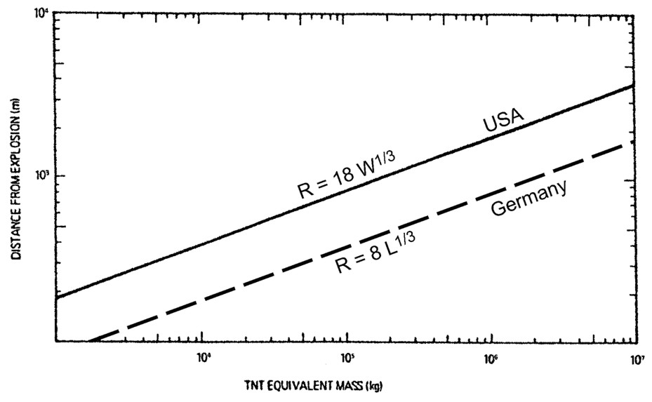
Fig 0 7: Safety distance as a function of the quantity of released liquefied gas according to the BMI guideline and the US regulatory guide 1.91, from [Verfondern, 2004]
With regard to mitigation of hydrogen explosions, the main knowledge gap may be the lack of identified useful methods for mitigation. Whereas numerous methods can be applied for hydrocarbon gas explosion mitigation, few of these will have a sufficient beneficial effect on hydrogen flames.
Due to the lack of good ways to mitigate hydrogen explosions, efforts to avoid significant flammable clouds to build up in partially confined and congested areas should have a main focus.
Some areas where increased understanding could help to estimate the risk better, is for instance to get a better understanding of spontaneous ignition phenomena. If larger high-pressure hydrogen leaks would always ignite within fractions of a second, like seen in some jet release experiments by [Groethe, 2006], this would be important for the estimated risk and risk reduction measures for such situations. The implication would be that for such releases, there is no point to work actively to minimize ignition sources, there is too little time for any action to be taken, and fortunately, there is no risk for a very large gas cloud to be generated. More work will be needed to understand these phenomena better.
It is unclear under what conditions, such as volume size, aspect ratios, and obstructions, etc., the mitigation by explosion venting would be applicable for hydrogen. Available vent-sizing methods and guidelines have very limited applicability for hydrogen. More experimental data and analysis is necessary.
Available guidelines on safety distances related to siting of hydrogen facilities are controversial and do not provide clear input.
Water deluge is potentially a mitigation measure that could reduce the flame speeds and explosion severity. This measure works very well for natural gas explosions, provided the degree of confinement of the gas cloud is limited. Potentially, there will also be situations where water deluge may mitigate hydrogen flames, this should be investigated experimentally at realistic scales.
One possibly very critical situation will be a massive release of liquid hydrogen on a warm day with low humidity. In such a situation the evaporated gas cloud may form a neutral or dense hydrogen-air cloud, which may represent a very significant hazard, in particular if it will become filled with obstacles or become partly confined. Typical obstacles could be a forest, a process plant, industrial or domestic houses etc. One possibility to mitigate this hazard will be to introduce sufficient heat to the cold evaporated hydrogen-air mixture for it to become more buoyant. This can for instance be done by water spray systems with small droplets to maximize the heat transfer. For the increased understanding of this hazard, it would be useful to see large-scale experiments which both demonstrates the possibility to generate a dense gas hydrogen-air mixture on a warm day with low humidity, and then repeat the experiment applying water sprays to add heat to the plume.
Another critical situation is the transport of significant amounts of hydrogen through tunnels. If significant leaks may take place, or if the gas is on purpose released in an emergency situation, the confinement of the tunnel may make this a severe risk scenario. For situations with significant releases of hydrogen inside a tunnel, no good mitigation methods have been identified so far.
The best method for mitigation of risk is to build up a good understanding of physics and to be able to model the various risk reduction methods available. With a CFD-tool available that can model the consequences of a given incident, as well as the consequences of mitigated incidents, one will have the possibility to optimize the design and mitigation methods for the situations considered. When doing so, it is important not only to consider one particular incident, but to study the range of possible incidents, to estimate the overall effect of mitigation measures. Optimally, a probabilistic risk assessment could be carried out, in which the effect of mitigation is assessed. This could e.g. be along the lines recommended for Norwegian offshore installations [Norsok, 2001]. To follow this approach, a validated CFD-tool will be required, which can model as much as possible of the phenomena and mitigation methods of interest.
|
Reference& sources: [Bevilagua, 2001] Bevilaqua Knight Inc., Bringing Fuel Cell Vehicles to Market, Scenarios and Challenges with Fuel Alternatives. Consultant Study Report, Hayward, USA (2001). [BMI, 1976] BMI Bundesministerium des Innern. Bekanntmachung der Richtlinie für den Schutz von Kernkraftwerken gegen Druckwellen aus chemischen Reaktionen durch Auslegung der Kernkraftwerke hinsichtlich ihrer Festigkeit und induzierter Schwingungen sowie durch Sicherheitsabstaende, September 13, 1976. [Hord 1978] Hord, J., How Safe is Hydrogen. Symp. on Hydrogen for Energy Distribution, Chicago (1978). [US-DOT, 1997] US-DOT. Department of Transportation. Clean Air Programm, Use of Hydrogen to Power the Advanced Technology Transit Bus (ATTB): An Assessment. Report DOT-FTA-MA-26-0001-97-1 (1997). [US-NRC, 1978] US-NRC. Evaluations of Explosions Postulated to Occur on Transportation Routes Near Nuclear Power Plants, Regulatory Guide 1.91, Revision 1, U.S. Nuclear Regulatory Commission (1978). [Verfondern, 1999] Verfondern, K., Hydrogen as an Energy Carrier and its Production by Nuclear Power, Report IAEA-TECDOC-1085, International Atomic Energy Agency, Vienna, Austria (1999). [Verfondern, 2004] Verfondern K., Nishihara T., Valuation of the Safety Concept of the Combined Nuclear/Chemical Complex for Hydrogen Production with HTTR, Report Juel-4135, Research Center Juelich, Germany (2004). [Westfalen, 2001] Westfalen AG. Aufstellen oder Einlagern von Fluessiggas-Behaeltern, Muenster, Germany, Company’s Pamphlet (2001). [Zabetakis, 1960] Zabetakis M.G., Burgess D.S., Research on the Hazards Associated with the Production and Handling of Liquid Hydrogen. Report WADD TR 60-141. Wright Air Development Division, Wright Patterson Air Force Base, Ohio, USA (1960). [Sherman, 1989] Sherman, M.P., Tieszen, S.R. and Benedick, W.B, FLAME Facility, The Effect of Obstacles and Transverse Venting on Flame Acceleration and Transition to Detonation for Hydrogen-Air Mixtures at Large Scale, Sandia National Laboratories, Albuquerque, NM 87185, USA, NUREG/CR-5275, SAND85-1264, R3, April 1989. [Norsok, 2001] NORSOK Z-013, 2001. Risk and emergency preparedness analysis, Norsok standard. Available from Standard Norge, Postboks 242, N-1326 Lysaker, Norway. [Groethe, 2006] M. Groethe, E. Merilo, J. Colton, S. Chiba, Y. Sato, H. Iwabuchi: “Large-scale Hydrogen Deflagrations and Detonations,” International Journal of Hydrogen Energy, 31, 2006. |
The generic approach of layers and barriers can be used for hydrogen refilling stations for instance. In this case the list of initiating events is grouped as per the safety and barriers paragraph and the end states of various scenarios consider the damage and harms as defined in previous chapters. The damage states for a given release path are associated with risk levels. Quantification provides list of combination of failures leading to a certain risk status of the installation. The work is still under development for tasks HyQRA by various participants at the exercise and future revisions will include details and results as confirmed by various methods.
<< | Content | >>