
|
BRHS /
Fundamentals of hydrogen combustionPremixed combustion of hydrogen-air mixturesLaminar premixed flamesStructure of the reaction zone and flame temperature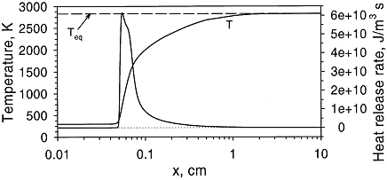 Figure 1. Distributions of temperature and heat-release rate in the \mathrm{H_2}-\mathrm{O_2} flame. From Liu, Guo, Smallwood & Gulder (2002) (LiuF:2002). The study of the laminar flame structure is of fundamental interest in combustion science. It is also a necessary first step towards understanding combustion processes. In turbulent combustion, for example, there are many occasions where chemical reactions are localised in laminar flames that are being wrinkled and perturbed by turbulence. While entire monographs have been devoted to detailed experimental studies of the structure (e.g Fristrom (1995) (FristromRM:1995)) there appears to be no focus on hydrogen combustion. Studies of the flame stucture are quite difficult as laminar flames are very thin and complex. 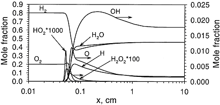 Figure 2. Distributions of mole fraction of species in the \mathrm{H_2}-\mathrm{O_2} flame. From Liu, Guo, Smallwood & Gulder (2002) (LiuF:2002). The internal flame structure is known to depend on the chemical kinetics of the combustion reactions, and, thermodynamic as well as transport properties of all species in the flame. Solutions of the conservation equations of mass, energy and chemical species by means of numerical codes (e.g. Kee, Rupley & Miller (1987) (KeeRJ:1987) and Kee, Rupley & Miller (1989) (KeeRJ:1989)) are being used to resolve the details of the flame structure. The thermo-chemical and transport properties of the species are included via databases into the codes. The reaction mechanisms used in the simulations are taken from separate studies. An example of results obtained in this way is given by Figure 1 and Figure 2, showing distributions of temperature, heat release and species concentrations in a rich \mathrm{H_2}-\mathrm{O_2} premixed flame with an equivalence ratio of 2 at atmospheric conditions (after Liu, Guo, Smallwood & Gulder (2002) (LiuF:2002)). A characteristic feature of the heat release in the flame is its sudden start caused by the chain branching reaction \mathrm{O} + \mathrm{H_2} \rightarrow \mathrm{H} + \mathrm{OH}
initiated by the rate limiting reaction \mathrm{H} + \mathrm{O_2} \rightarrow \mathrm{O} + \mathrm{OH}
having an activation energy of about 17 kcal/mole. Very quickly after the start of the chain branching reactions a high concentration of radicals is reached within the flame followed by a slow and extended, three molecular radical recombination zone where reactions like \mathrm{H} + \mathrm{OH} + \mathrm{M} \rightarrow \mathrm{H_2O} + \mathrm{M}
\mathrm{H} + \mathrm{H} + \mathrm{M} \rightarrow \mathrm{H_2} + \mathrm{M}
\mathrm{O} + \mathrm{O} + \mathrm{M} \rightarrow \mathrm{O_2} + \mathrm{M} \quad \text{etc.}
lead to final equilibrium. The heat relase during the conversion from reactants to products causes the temperature to rise (see Figure 3). 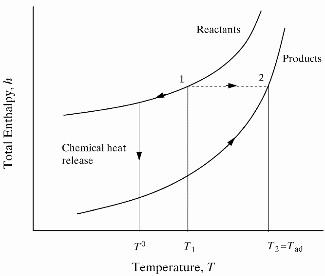 Figure 3. The principle of energy conservation during the conversion of reactants into products during combustion. From Law (2006) (LawCK:2006a). In the absence of heat losses to the surroundings, the final temperature attained is called the adiabatic flame temperature, T_f^{\scriptsize \text{ad}} (see Figure 3). More specifically, if a given uniform mixture with an initial temperature and composition is made to approach chemical equilibrium through an adiabatic, isobaric process at pressure P, then the final temperature is called the adiabatic flame temperature, T_f^{\scriptsize \text{ad}} (see page 37 of Law (2006) (LawCK:2006a)). When an adiabatic combustion process is isochoric instead of isobaric, i.e. when the volume occupied by the product mixture equals that of the reactant mixture prior to combustion, the final flame temperature T_f^{\scriptsize \text{ad,cv}} is larger than T_f^{\scriptsize \text{ad}}. The larger value of T_f^{\scriptsize \text{ad,cv}} stems from the fact that no work is done on the surroundings during isochoric combustion. All energy released by the chemical reactions is invested in raising the temperature of the mixture. Conversely, during isobaric combustion the hot product gases have to displace the surrounding air for the pressure to remain constant. A portion of the energy released by the chemical reactions that is consumed to displace the surroundings becomes unavailable for heating the mixture. 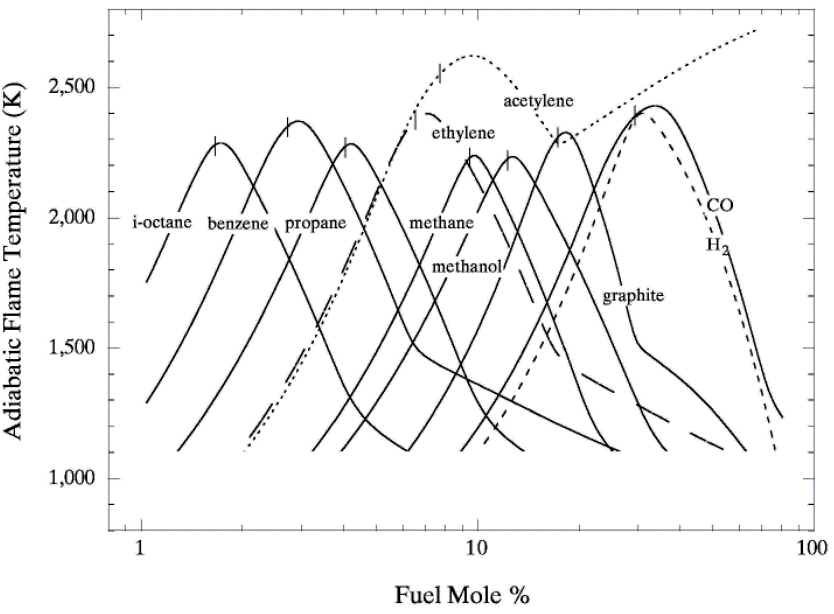 Figure 4. Adiabatic flame temperature, T_f^{\scriptsize \text{ad}}, as a function of the mole percent of fuel for several fuel–air mixtures at initial conditions of 1 bar and 298.15 K. The vertical bars indicate stoichiometric concentrations. From Law (2006) (LawCK:2006a). Figure 4 illustrates the behaviour of the adiabatic flame temperature, T_f^{\scriptsize \text{ad}}, as a function of mixture composition for a variety of fuels mixed with air. With all fuels the following trend is observed: the adiabatic flame temperature attains a maximum at a fuel concentration slightly above the stochiometric value, and levels off as the fuel concentration approaches the flammability limits. When T_f^{\scriptsize \text{ad}} is plotted against the fuel concentration, the locations of the flame temperature curves are seen to be scattered along the the horizontal axis. However, when these curves are plotted against the equivalence ratio, as is done in Figure 5, their apearance becomes more systematic because the stoichiometric concentration of all fuels coincide at \phi=1. The flame temperature curves are also seen to behave in a manner that allows them to be expressed by matematical relationships as a function of the equivalence ratio \phi=1. For fuel-lean mixtures at moderate pressures and temperatures of up to 2300 - 2400 K, the dissociation of product species is negligible and the product composition can be estimated from the overall chemical equation. This makes the calcualtion of the adiabatic flame temperature easier. Furthermore, the adiabatic flame temperature can approximated by simple formulas like the one developed by Chang & Rhee (1983) (ChangSL:1983) in the form: T_f^{\scriptsize \text{ad}} =a\cdot \left[1+b\cdot \mathrm{ln} \phi +c\cdot \left(\mathrm{ln} \phi \right)^{2} \right]
where
In the above expressions P, \phi and m respectively denote the pressure, equivalence ratio and mass. The coefficients for hydrogen-air mixtures are: a_{1} =2412.2 K; a_{2} = 17.9 K; b_{1} = 0.473 K; b_{2} = 0.021 K; c_{1} = 0.0217 K; and c_{2} = 0.0191 K. 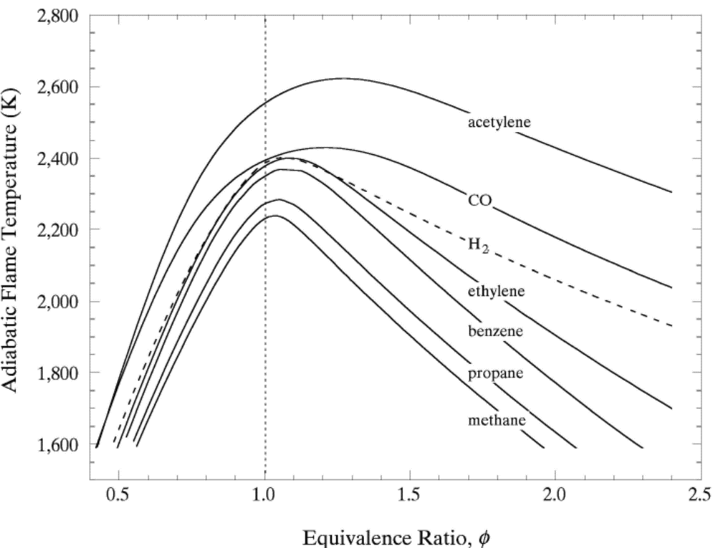 Figure 5. Adiabatic flame temperature, T_f^{\scriptsize \text{ad}}, as a function of fuel equivalence ratio, \phi, for several fuel–air mixtures at initial conditions of 1 bar and 298.15 K. From Law (2006) (LawCK:2006a). At higher pressure and temperature, and, with rich mixtures, the product mixture contains many more species because of dissociation. The composition of the products can then only be estimated by large reaction sets. Specialised chemical equilibrium codes then become a necessity to compute the adiabatic flame temperature. Bibliography Chang S.L. and Rhee K.T. (1983) Adiabatic flame temperature estimates of lean fuel/air mixture. Combustion Science and Technology, 35:203-206.(BibTeX) Laminar burning velocity and laminar flame thicknessLaminar flames propagate via the diffusion of heat and free radicals from the reaction zone to the unburned mixture ahead of it to effect ignition. The diffusion flux depends on the temperature gradient (which in turn depends on the reaction rate) and the various transport coefficients for the different species. The pressure remains practically constant across a laminar flame, hence the flame temperature corresponds closely to the product temperature for a constant pressure adiabatic process. The quantitative description of a laminar flame requires a detailed knowledge of the chemical kinetics, transport coefficients, and the thermochemical data of the various chemical species involved in the reactions. Thus, the laminar burning velocity provides a fundamental parameter whereby one can assess one's knowledge of the combustion process of a given explosive mixture. There are various methods for the experimental measurement of the laminar burning velocity but each has certain advantages and disadvantages. 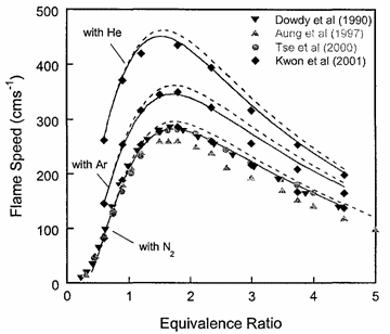 Figure 1. Laminar flame speed at 298 K and 1 atm for \mathrm{H_2}-\mathrm{O_2} mixed with \mathrm{N_2}, \mathrm{He} and \mathrm{Ar} (\mathrm{O_2}:\mathrm{N_2} = \mathrm{O_2}:\mathrm{He} = \mathrm{O_2}:\mathrm{Ar} = 1:3.76). From Lee (2006) (LeeJHS:2006). The solid and dashed lines are predicted values obtained with chemical kinetic mechanisms. Since the laminar burning velocity depends on curvature and flow straining, the correct laminar burning velocity is often difficult to determine. Flame instability also adds to the difficulty of the experimental measurement of the laminar burning velocity especially in the composition range where the flame is cellular. Theoretical computation of the laminar burning velocity is possible provided that the flame chemistry, transport coefficients and the thermochemical data are known. There are standard computer codes (e.g. CHEMKIN) available for such purposes. In general, the weakest link is usually associated with the inadequate modelling of the detailed flame chemistry. In fact, experimental burning velocity data is used to validate theoretical models of the detailed flame chemistry. For hydrogen-oxygen mixtures, the flame chemistry is perhaps the most well-established compared to the other common hydrocarbon fuels. A comparison between theoretical and experimentally measured values is given in Figure 1 for hydrogen-oxygen mixtures using various inert diluents (i.e. argon, helium, and nitrogen). The excellent agreement indicates that the chemistry of hydrogen-oxygen flames is now quite well-established. In Figure 1 it is also seen that the maximum laminar burning velocity for hydrogen-oxygen-nitrogen (or -air) mixtures is about 300 cm/s which is approximately six times that of most of the common hydrocarbon fuels of the order of 40 cm/s. This is a result of the high diffusivity of hydrogen, accounting for the shift of the maximum burning velocity towards richer mixtures. For the common hydrocarbon fuels, the maximum burning velocity occurs at just slightly richer than stoichiometric composition. It should be noted that laminar flame models also provide the fundamental basis for the modelling of turbulent flames. Also, a good understanding of the flame chemistry is essential to the choice of inhibitors for the suppression of explosions. For hydrogen-oxygen mixtures the flame chemistry is adequately known (Lee (2006) (LeeJHS:2006)). The magnitude of the laminar burning velocity is determined experimentally. Techniques of measuring flame velocity may be categorised as folows:
The advantages and disadvantages of these methods have been described by Koroll, Kumar & Bowles (1993) (KorollGW:1993):
A rudimentary way to estimate the laminar flame thickness rests on the assumption thatflame propagation is driven by heat conduction only (PoinsotT:2001): \delta_L = \frac{\lambda_u }{\rho_u {C_\mathrm{P}}_u} \frac{1}{{S_u}_L}
Here \delta_L denotes the laminar flame thickness; \lambda_u, \rho_u and {C_\mathrm{P}}_u} respectively denote the thermal conductivity, density and specific heat of unburnt (fresh) mixture; and, {S_u}_L the laminar burning velocity. Estimates obtained in this manner have been found to underestimate the real flame thickness by a factor of five. Similar expressions to estimate the laminar flame thickness have also been proposed by Blint (1986) (BlintRJ:1986) (see pages 57 and 58 of Poinsot & Veynante (2001) (PoinsotT:2001)). 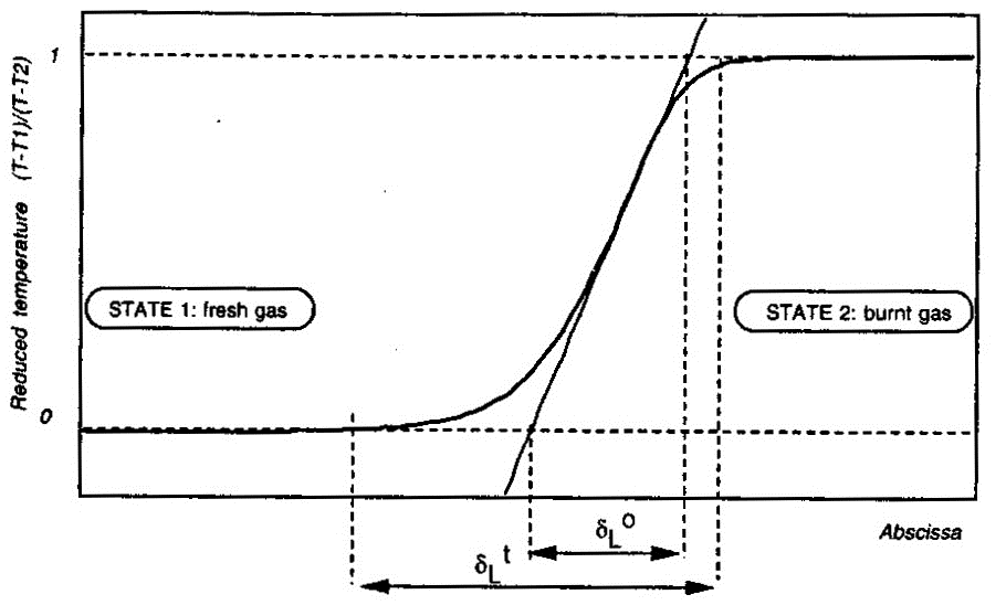 Figure 2. Definition of the laminar flame thickness. From Poinsot & Veynante (2001) (PoinsotT:2001). More accurate values for the laminar flame thickness may be obtained from the numerical solution of the governing equations applied to the flame structure. An example of flame thickness of hydrogen-air mixtures obtained in this manner is by Aung, Hassan & Faeth (1997) (AungKT:1997). These authors report the following magnitudes for the unstretched laminar flame thickness \delta_L^{\circ} at normal temperature and pressure: \delta _L^{\circ} = 0.65 mm for equivalence ratio \Phi = 0.40 ; \delta _L^{\circ} = 0.35 mm for \Phi = 0.70 and \delta _L^{\circ} = 0.43 mm for \Phi = 4.0 . The unstretched laminar flame thickness \delta_L^{\circ} is defined as follows (Poinsot & Veynante (2001) (PoinsotT:2001)) and illustrated by Figure 2: \delta_L^{\circ} = \frac{T_2-T_1}{\mathrm{max}\left(\left|\partial T/\partial x\right|\right)}
There is also another laminar flame thickness as illustrated by Figure 2: the total thickness \delta _L^{\scriptstyle \mathrm{t}} . This quantity is defined as the distance over which the reduced temperature \theta = (T - T_1)/(T_2 - T_1) changes from 0.01 to 0.99; but this quantity is not very useful for modeling purposes (Poinsot & Veynante (2001) (PoinsotT:2001)). Its definition creates a long temperature tail which does not correspond with the species profiles across the flame structure. Aung K.T., Hassan M.I. and Faeth G.M. (1997) Flame stretch interactions of laminar premixed hydrogen/air flames at normal temperature and pressure. Combustion and Flame, 109:1-24.(BibTeX) Flame stretch and effect of flame curvature, Markstein lengthsFlame front propagation in a non-uniform flow is affected by strain and curvature effects, which lead to the change in the flame area and measured by flame stretch, which is a fractional rate of change of a flame surface element: k = \frac{1}{A}\frac{{dA}}{{dt}},
where k \ - flame stretch, A – area of the flame surface element, t - time. Asymptotic theories, e.g. (MarksteinGH:1964), (WilliamsFA:1985), (ClavinP:1985) suggest that the flame stretch (flame strain, or flame curvature, or both) may affect the laminar burning velocity and in the limit of the small stretch it controls the laminar burning velocity through the linear relationship: s_u = s_{u\infty } - L\,k, \ \ \ \ \ \ \ \ (1)
where s_u - laminar burning velocity, s_{u\infty } - laminar burning velocity of planar unstretched flame, L – Markstein length, k - stretch rate. The above expression is often recast in the following form: \frac{{s_u }}{{s_{u\infty } }} = 1 - Ma \cdot \frac{{k\delta }}{{s_{u\infty } }} = 1 - Ma \cdot Ka , \ \ \ \ \ \ \ \ (2)
where Ma=L/\delta - Markstein number, \delta = {{\lambda _u } / {\left( {\rho _u \,c_p s_{L\infty } } \right)}} - characteristic flame front thickness, Ka = k \delta / s_{u\infty } - Karlovitz number. Formally a linear dependence between the burning velocity s_u and the stretch rate k , which is a result of a theoretical analysis, is valid only for small stretch rates ( Ka << 1 ). In fact, a non-linear relationship between and k is found for a broader range of k (AungKT:1997). 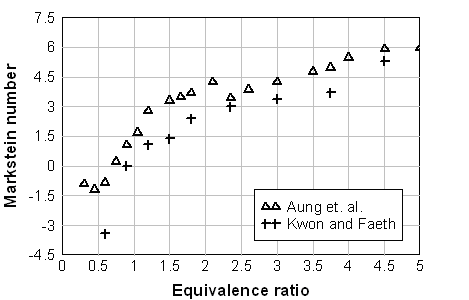 Fig. 1. Markstein number of the hydrogen-air flame at normal pressure and temperature as a function of the equivalence ratio \Phi . (AungKT:1997), (KwonOC:2001). The sign of the Markstein length (Markstein number) controls the preferential-diffusion stability of the laminar flame fronts. Equations (1), (2) readily demonstrates the relationship between the stretch and preferential-diffusion instability: if the Markstein length (Markstein number) is negative then the laminar burning velocity increases as the flame stretch increases. This causes bulges in a flame front with a positive stretch to grow further and thus the flame is unstable. If the Markstein number is positive, then the laminar burning velocity decreases with increasing stretch and similar bulges in the flame surface become smaller, so that flame become stable to preferential-diffusion instability. Hydrogen flames are unstable in learn mixtures. Figure 1 shows the Markstein number of H2-air flames as a function of the equivalence ratio \Phi ; at normal temperature and pressure reported in (AungKT:1997) and (KwonOC:2001). The neutral preferential-diffusion condition is at equivalence ratio \Phi=0.7-0.9 . With increase of pressure the Markstein length L becomes positive at larger equivalence ratios (KwonOC:1992), (TseSD:2000). Markstein length of H2-air flames was reported in (DowdyDR:1990), where it changed from about –0.4 mm at \Phi=0.3\ (~10% H2) and up to 0.5 mm at \Phi=2.3\ (~68%). Poinsot T. and Veynante D. (2001) Theoretical and numerical combustion. Edwards, Philadelphia.(BibTeX) Flame cellular structure and wrinklingDuring experimental measurements of the H2-air burning velocities three kind of instabilities, leading to appearance of flame wrinkling, were usually observed: preferential-diffusion instability (when Markstein length L and Markstein number Ma are below zero), hydrodynamic instability and buoyant instability (AungKT:1997), (KwonOC:2001). The preferential-diffusion instability creates irregular (chaotic) distortion, leading to formation of irregular flame surface, larger flame front area and faster propagation of the stretched flames. Under the stable preferential-diffusion conditions propagation of the initially smooth flame front is followed by onset of the regular cellular structure, formed by hydrodynamic instabilities. Detailed review and analysis of the hydrodynamic instabilities in the spherically propagating premixed flames are given in the work by Bradley and co-workers {[DB, BradleyD:1994b]}, (BradleyD:1999), (BradleyD:2000). They considered a spherical premixed flame as a fractal surface, formed by the hydrodynamics instabilities. Hydrodynamic instability appears first as a cracking of the flame surface, then followed by development of a cellular flame structure and flame wrinkling. As the flame propagates the wrinkling increases and creates a larger surface area and consequent flame acceleration. As a result, the flame speed increases as a square root of elapsed time. If a flame radius is large enough, the turbulent flame appears. According to Bradley (BradleyD:1999) hydrodynamic instabilities arise at the larger wavelengths and cascade down through a range of ever decreasing wavelengths to be stabilised at the smallest wave-length by thermo-diffusive effects. The largest instability is bounded only by the physical scale of the problem and the outer cut-off is expected to be of the order of the flame front radius. The inner cut-off of is expected to be of the order of the real flame front thickness. Semi-empirical correlation is given in (BradleyD:1999) for the critical Peclet number Pe_{cl} , characterising the onset of cellular structure for freely propagating flames: Pe_{cl} = 177Ma+2177 for -5 <Ma<8 , where Pe=r s_u / \nu_u - Peclet number, r - flame radius, s_u - burning velocity, \nu_u - kinematic viscosity of unburnt (fresh) mixture. It is possible to show that for a wide range of mixtures the onset of instabilities occurs at a flame radius of order 10 cm and the minimum cell size is below 1 cm. Conclusions of this analysis can be applied only to the stable preferential-diffusion conditions. The flames with unstable preferential- diffusion conditions do not have the coherent cellular structure and the mechanism of their surface distortion cannot be explained by hydrodynamic instability alone (KwonOC:1992). 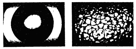 Fig. 1. Shadowgraph of the H2/O2/N2 flame surface for stable preferential-diffusion conditions ( \Phi=3.27 ). Left image for Pe > Pe_{cl} ; right image for Pe > Pe_{cl} . 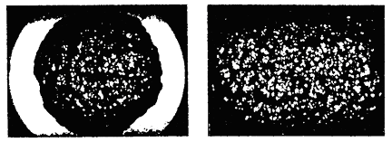 Fig. 2. Shadowgraph of the H2/O2/N2 flame surface for unstable preferential-diffusion conditions ( \Phi=1.00 ). Left image for Pe > Pe_{cl} ; right image for Pe > Pe_{cl} . The characteristic flame shape, corresponding to the thermodiffusively stable and unstable flames, is shown in Fig.1, 2, adopted from (KwonOC:1992) (with permission). Freely propagating flames are subject to natural convection. Analysis of convection instabilities was conducted by Babkin et. al. (BabkinVS:1984). It was demonstrated that the natural convection deforms the flame front in the case when the Froude number is above the critical value: Fr = {{s_u^2 } / {\left( {g\,D} \right)}} > 0.11,
where D is the critical diameter of the flame front. Under effect of natural convection the flame front initially becomes flatter at the lower part, the flame front rises as a whole in upward direction. Then the lower flat part of the flame bends inside, forming vortical flame structure. The fluid flow around naturally convected vortical flame creates the flame stretch, which is known to suppress formation of the cellular structure and flame wrinkling due to hydrodynamic instabilities. Aung K.T., Hassan M.I. and Faeth G.M. (1997) Flame stretch interactions of laminar premixed hydrogen/air flames at normal temperature and pressure. Combustion and Flame, 109:1-24.(BibTeX) Dependence of burning velocity on hydrogen concentration, pressure and temperatureDahoe (DahoeAE:2005) gives an extensive comparison of the laminar burning velocities of hydrogen mixtures, obtained in (LawCK:1993), (TakahashiF:1983), (WuCK:1984), (IijimaT:1986), (DowdyDR:1990), (EgolfopoulosFN:1990), (KorollGW:1993), (VagelopoulosCM:1995), (AungKT:1997), (TseSD:2000), (KwonOC:2001), (LamoureuxN:2002). Dependence of the laminar burning velocity on equivalence ratio (H2 concentration) at normal pressure and temperatures T = 293 - 298 K , adopted from (DahoeAE:2005), is shown in Figure 1. 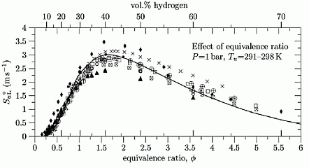 Figure 1. Effect of hydrogen concentration (expressed in equivalence ratio) on the laminar burning velocity of hydrogen–air mixtures, reproduced from (DahoeAE:2005) (with permission). The H2 combustion has a unique combustion properties:
Accurate measurement of H2 burning velocity is not possible for concentrations below downward flame propagation limit 9% of H2 since anisotropic flame propagation occurs in near-limit mixtures (KorollGW:1993). Liu and MacFarlane (LiuDDS:1983) obtained burning velocities within steam concentration range 0-15%. An empirical correlation by Liu and MacFarlane developed to describe the H2-air-steam burning velocity as a function of hydrogen concentration, steam concentration and temperature, is given below: s_u = BT_u ^C \exp \left( {D\,x_{H_2 O} } \right), \ \ \ \ \ \ \ \ \ (1)
where s_u – laminar burning velocity, m/s, B, C, D – coefficients, T_u – temperature of unburned gas in K, x - volumetric fraction of the species (H2 – hydrogen, H2O - steam). Coefficients for the correlation are given in Table 1. The reported root mean square deviation of the correlation is 0.189 m/s. The authors suggested that the correlation may be applied in the whole range of hydrogen flammability limits 5-75% volume and steam concentration range 0-25% volume; experimental temperature range was 293-523K. Reported by the authors root mean square deviation of the correlation is 0.189 m/s. They suggested that the correlation may be applied in the whole range of hydrogen flammability limits 5-75% and steam concentration range 0-25%; experimental temperature range was 293-523K. 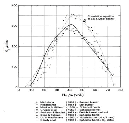 Figure 2. Laminar burning velocity of hydrogen air mixtures at room temperature and atmoshpheric measured by various methods. Solid line computed values for spherical flame propagation; dotted line correlation equation of Liu and MacFarlane. Table 1. Coefficients in the burning velocity correlation, eq. (1).
Combustion of H2-air-steam mixtures was studied later by Koroll et. al. (KorollGW:1993) within a steam concentration range 12-42% and Lamoureux et. al. (LamoureuxN:2002), who measured burning velocity with steam concentrations 10, 20, 30%. Koroll et. al. developed a correlation for burning velocity of H2-O2-diluent and H2-O2-diluent/steam mixtures, which is applicable in H2 concentration range 9% - 70%. Burning velocity of H2-O2 mixtures and hydrogen-fuelled mixtures with diluents were studied by Kwon et. al (KwonOC:1992) - H2-O2-N2 mixtures, Koroll et. al. (KorollGW:1993) - H2-air-diluent mixtures (normal pressure and temperature, hydrogen concentration range 9-70%, empirical correlation for S_u is given), Tse et. al. (TseSD:2000) - H2-O2-diluent mixtures, Kwon and Faeth [[DB, KwonOC:2001]} - H2-O2-diluent mixtures. Effect of steam and combined (CO2 + He) diluent on the burning velocity was studied in (LamoureuxN:2002) at T = 353K. Experimental data on the burning velocity at elevated pressures may be found in research by Iijima et. al. (IijimaT:1986), Kwon et. al. (AungKT:1997) – 3 atm, Tse et. al. (TseSD:2000) – up to 20 atm, Qin et. al. (QinX:2000) – up to 5 atm, Kwon and Faeth [[DB, KwonOC:2001]} – up to 3 atm, Kuznetsov et al. Invalid BibTex Entry! - up to 70 atm. Experimental data on the burning velocities at elevated temperatures are given by Liu and MacFarlane (LiuDDS:1983) – in the range 295K – 523K, Koroll et. al. (KorollGW:1993) – at temperatures 298K and 373K, Lamoureux et.al. (LamoureuxN:2002) – at temperatures 298K and 353K, Kuznetsov et. al. Invalid BibTex Entry! - at temperatures up to 573K. The cited studies used following experimental techniques. Optically accessed spherical flame propagation in a closed vessel was employed for velocity measurements in (DowdyDR:1990), (KwonOC:1992), (AungKT:1997), (TseSD:2000), (KwonOC:2001), (LamoureuxN:2002). In [DB, IijimaT:1986], (MiltonBE:1984), (DahoeAE:2005) the burning velocities were obtained using measurement in of pressure variation caused by confined deflagration in a windowless chamber. Double-kernel technique was used in (KorollGW:1993). Stabilised flames were used in (WuCK:1984) - stagnation flame and Bunsen burner, (EgolfopoulosFN:1990), (VagelopoulosCM:1995) - counterflow technique, (LiuDDS:1983) – constant velocity nozzle, (QinX:2000) – nozzle burner. Laminar burning velocities may be computed using fundamental kinetic and thermodynamic data. Comparison of the burning velocities predicted using different reaction mechanisms and software codes against experimental data may be found, e.g. in the papers (LiuDDS:1983), (EgolfopoulosFN:1990), (DowdyDR:1990), (VagelopoulosCM:1995), (AungKT:1997), (TseSD:2000), (QinX:2000), (KwonOC:2001), (LamoureuxN:2002), (DahoeAE:2005). 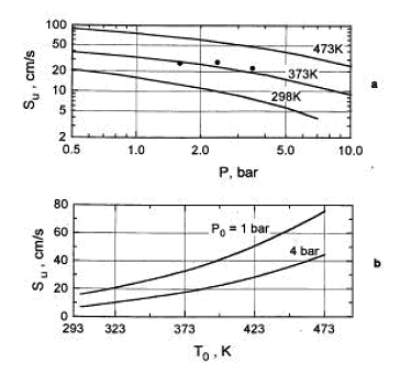 Figure 3. Laminar burning velocity as a function of pressure (a) and temperature (b) for 10% H2-air mixture (φ = 0.26.) The dependence of the laminar burning velocity on pressure and temperature is usually expressed as a polynomial function (PoinsotT:2001): s_u \left( {p,T} \right) = s_u \left( {p_0 ,T_0 } \right)\,\left( {\frac{p}{{p_0 }}} \right)^n \left( {\frac{T}{{T_0 }}} \right)^m,
where s_u \left( {p_0 ,T_0 } \right) - burning velocity at initial pressure p_0 and temperature T_0 , s_u \left( {p,T} \right) - burning velocity at actual pressure p and temperature T , m, n – temperature and baric indexes in dependence of the burning velocity correspondingly. In case, where combustion process may be assumed as adiabatic (e.g., spherical flame propagation in a closed vessel) and temperature changes only due to adiabatic compression, the dependence for the burning velocity may be expressed as a function of pressure only: s_u \left( {p,T} \right) = s_u \left( {p_0 } \right)\,\left( {\frac{p}{{p_0 }}} \right)^\varepsilon ,
\varepsilon = m_0 + n_0 - m_0 /\gamma _u - overall thermokinetic index, \gamma = {{c_p } / {c_v }} - specific heat ratio, c_p, c_v - specific heats at constant pressure and constant volume correspondingly. Values of baric, thermal and overall indexes, which may be recommended according to (BabkinVS:2003), are given in Table 2. The burning velocity increases rapidly with increase of temperature and just slightly - with increase of pressure (except for mixtures close the flammability limits). Table 2. Baric, thermal and overall thermokinetic indexes for H2-air laminar burning velocity ( p_0 = 1 atm, T_0 = 298K )
* - values in brackets are interpolated or extrapolated, ** - values determined in the range p=0.25-1.0 atm. In the range of H2 concentration 60-70% values n=(-0.4) – (-0.1) may be expected, (GrumerJ:1959). In paper by Iijina and Takeno (IijimaT:1986) following temperature and baric index values were reported: m = 1.54 + 0.026(\Phi - 1),
n = 0.43 + 0.003(\Phi - 1).
For stoichiometric mixture Dahoe (DahoeAE:2005) found following temperature and baric indexes using inverse problem method: m = 140.0 \pm 3.7 \cdot 10^{-2},
m = 194.0 \pm 4.4 \cdot 10^{-3}.
Dahoe A.E. (2005) Laminar burning velocities of hydrogen-air mixtures from closed vessel gas explosions. Journal of Loss Prevention in the Process Industries, 18:152-166.(BibTeX) Content: Fundamentals of hydrogen combustion Turbulent premixed flamesTurbulence scalesAlthough a huge number of theoretical, experimental and computational investigations on turbulence have been performed, the structure and description of turbulence still remain open issues. The motivation behind the study of turbulent flows is due to the fact that the vast majority of flows is turbulent and turbulence significantly increases the rates of transport and mixing of matter, momentum and heat in the flows (PopeSB:2000). Turbulence itself is a very complex phenomenon, involving different time and length scales. In the well-known energy-cascade theory, the kinetic energy enters the turbulence at the largest scales of motion through the production mechanism. This energy is transferred from the largest scale (integral scale) to smaller and smaller scales until it is dissipated by viscous action at the smallest scale, the so-called Kolmogorov length scale. The wide range of length-scales and time-scales, the production, the dissipation and the energy transfer between different length-scales make the modelling of turbulence one of the greatest scientific challenge. The level of difficulty in investigating premixed flames is greatly enhanced when also turbulence comes into play, because of the complex interactions between the turbulence itself and the combustion. The transfer rate of kinetic energy per mass unit of fluid over any particular scale between the macro structure and the micro structure obeys the relationship (this is known as Kolmogorov’s law), e.g., (BatchelorGK:1993): \varepsilon =-\frac{d}{dt} U_{}^{2} =A\frac{U_{}^{3} }{L} \ \ \ \ \ \ (1)
where A is a constant in the order of unity. Together with the root-mean-square of the instantaneous velocity fluctuations, this expression can be used to characterise the macro structure in terms of a macro velocity scale, a macro length scale and a macro time scale: u_{t} = u_{rms}^{,} \quad \quad \ell _{t} =\frac{{u_{rms}^{,}}^{3} }{\varepsilon } \quad \quad \tau _{t}^{} =\frac{{u_{rms}^{,}}^{2} }{\varepsilon }
The microstructure can be characterised by the Kolmogorov velocity, length and time scale: u_{K}^{} =\left(\nu \varepsilon \right)_{}^{1/4} \quad \quad \ell _{K}^{} =\left(\frac{\nu _{}^{3} }{\varepsilon } \right)_{}^{1/4} \quad \quad \tau _{K}^{} =\left(\frac{\nu _{}^{} }{\varepsilon } \right)_{}^{1/2}
where \nu denotes the kinematic viscosity. It should be noted that equation (1) describes the kinetic energy transfer on the larger scales as well as the viscous dissipation on the micro structure despite the apparent absence of the molecular viscosity. A combustion zone may also be characterised in terms of velocity, length and time scales. If the laminar burning velocity, the laminar flame thickness, and the chemical time scale: S_{u L} \quad \quad \delta _{L}^{} \quad \quad \tau _{c}^{} =\frac{\delta _{L}^{} }{S_{u L} } are taken as the fundamental scales of the combustion ((PetersN:1991), (BorghiR:1988)), the structure of a turbulent flame may be considered by relating these combustion scales to those of the turbulent flow field. The occurrence of a particular combustion regime is determined by the value of the Damkohler number: Da=\frac{L/U}{\tau _{c} } =\frac{\ell _{t} /u_{rms}^{'} }{\delta _{L} /S_{u L} } When the scales of the micro structure of the turbulent flow field are substituted for L and U, it constitutes the reciprocal Karlovitz number: Ka^{-1} =\frac{L/U}{\tau _{c} } =\frac{\ell _{K} /u_{K} }{\delta _{L} /S_{u L} } The Damkohler and Karlovitz number can be used to identify different combustion regimes [14, 15] by employing two dimensionless parameters, \left(\frac{u_{rms}^{,} }{S_{u L} } \right) and \left(\frac{\ell _{t}^{} }{\delta _{L}^{} } \right) and by rewriting their definitions into \frac{u_{rms}^{,} }{S_{u L} } = Da_{}^{-1} \left(\frac{\ell _{t}^{} }{\delta _{L}^{} } \right) (2) and \frac{u_{rms}^{,} }{S_{u L} } = Ka_{}^{2/3} \left(\frac{\ell _{t}^{} }{\delta _{L}^{} } \right)_{}^{1/3} (3) Since the expressions for the laminar burning velocity and the laminar flame thickness (DahoeAE:2003), \frac{S_{u L} }{S_{u L}^{o}} =\sqrt{\frac{\lambda (T_{u} )}{\lambda (T_{u 0} )} } \left(\frac{T_{u} }{T_{u 0}} \right)\left(\frac{P_{}^{} }{P_{0}^{} } \right)_{}^{\frac{n-2}{2} } \left(\frac{T_{f} }{T_{f}^{o} } \right)^{-\frac{n}{2} } \left(\frac{T_{f} }{T_{f}^{o} } \right)^{\frac{m}{2} } \exp \left[-\frac{Ea}{R} \left(\frac{1}{T_{f}} -\frac{1}{T_{f}^{o} } \right)\right] \frac{\delta _{L}^{} }{\delta _{L}^{o} } =\sqrt{\frac{\lambda (T_{u})}{\lambda (T_{u 0})} } \left(\frac{P }{P_{0}} \right)^{-\frac{n}{2} } \left(\frac{T_{f}}{T_{f}^{o} } \right)_{}^{\frac{n}{2} } \left(\frac{T_{f}^{} }{T_{f}^{o} } \right)_{}^{-\frac{m}{2} } \exp \left[+\frac{Ea}{R} \left(\frac{1}{T_{f}^{} } -\frac{1}{T_{f}^{o} } \right)\right] in conjunction with the definition of the thermal conductivity and the viscosity in terms of molecular properties imply that S_{u L} \delta _{L}^{} =\frac{\lambda }{\hat{C}_{P}^{} } =\frac{\mu }{\rho } a third relationship may be derived as \frac{u_{rms}^{,} }{S_{u L} } = Re\left(\frac{\ell _{t}^{} }{\delta _{L}^{} } \right)_{}^{-1} (4) Equations (2), (3) and (4) may then be used to construct a figure which is known as the Borghi diagram. Pope S.B. (2000) Turbulent flows. Cambridge University Press, Cambridge, United Kingdom.(BibTeX) Interaction between turbulence and flames: turbulent burning velocityAs if follows from the title a turbulent combustion is affected/dominated by the turbulence-chemistry interaction. The turbulence can promote the combustion by two main mechanisms: the larger turbulent length scales are capable of increasing the wrinkling of the flame, increasing the flame surface area and therefore the fuel consumption rate. If the Kolmogorov length scale of the flow is smaller than the flame thickness, the turbulence is also able to modify the inner flame structure, increasing the transport rate of heat and matter across the flame itself. It must be pointed out that in some cases turbulence decreases the combustion rate and it can even cause the quenching of the flame. Being the coupling between turbulence and chemistry a two way coupling, also the combustion affects the turbulent field. Across the flame, because of the heat release, a strong acceleration of the flow occurs, producing the so-called “flame generated turbulence”. Moreover the increase of temperature across the flame enhances the gas kinematic viscosity, damping the turbulence (relaminarization due to combustion). 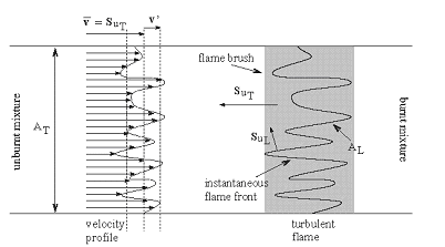 Figure 1. Turbulent burning velocity. To expose the features of turbulent flame propagation, it is helpful to consider laminar flame propagation briefly. When a flame is stabilised in a laminar flow of combustibles, it establishes itself at a fixed position in the flow field and its surface remains smooth. In other words, it inherits the laminar behaviour of the flow field. Moreover, the velocity at which the cold reactants enter the flame zone in the normal direction, the laminar burning velocity, appears to be a mixture specific property. It reflects the sensitivity of the combustion process to changes in the chemical composition, fuel concentration, oxygen content, pressure and temperature of the reactants. By contrast, when a laminar flame becomes trapped within a turbulent flow of combustibles, it inherits the turbulent nature of the flow field: the turbulence of the approaching flow continuously distorts the flame and ceaselessly shifts its position in space between certain geometrical boundaries. As a result, the surface area of the instantaneous laminar flame changes in a chaotic manner, which is determined by the turbulence of the flow field. The geometrical boundaries between which the instantaneous flame front shifts its position are identified as a turbulent flame thickness. A superposition of many instantaneous flame surfaces results in a time-averaged picture that is frequently referred to as the turbulent flame brush, and inspired the definition of a turbulent burning velocity by analogy with the laminar burning velocity. Due to the enhancement of heat and mass transfer by turbulence, the turbulent flame brush propagates with a turbulent burning velocity that is greater than the laminar burning velocity. The local consumption of reactants at any particular portion of the flame surface, however, occurs within a zone whose width is equal to the local laminar flame thickness and at a rate which is determined by the local laminar burning velocity. In the case of large scale, low intensity turbulence, the instantaneous flame front will be wrinkled while the transport properties remain the same. The wrinkles increase the flame front area per unit cross section of the turbulent flame brush which results in a higher propagation velocity without a change in the instantaneous local flame structure itself. The instantaneous flame surfaces in such a turbulent flame are known as laminar flamelets. With this picture in mind, Damkohler and Schelkin derived the earliest models for the turbulent burning velocity. These authors and later Karlovitz demonsterated that turbulent flame speed is defined byz the level of turbulence. Damkohler G. NACA Tech. Memo 1112, National Advisory Committee for Aeronautics, Washington, 1947. Original: Z. Elektrochem., vol. 46, 1940, pp. 601. Borghi-diagram and interpretation of combustion regimesDepending on the ratio between the burning velocity and the flame thickness of the combustion zone, if a flame were to establish itself in a laminar flow of combustibles, and the velocity and length scales of the turbulent flow, there exist various modes of flame propagation. A flame may propagate as a reacting surface containing small scale wrinkles (wrinkled flame), as a surface containing large scale wrinkles (corrugated flame), the flame zone may be disrupted into an assembly of pockets containing reactants only, combustion products only, or a mixture of both (distributed reaction zones), or, it may be smeared out in space (well-stirred reactor regime). Each of these combustion regimes is known to have a specific burning velocity and flame thickness dependence on turbulence. 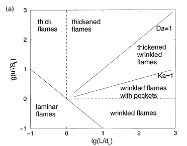 Figure 1. Borghi diagram of different combustion regimes The existence of different combustion regimes can be understood by considering the interaction between the turbulence scales and the instantaneous flame front, and with the aid of certain dimensionless groups that appear in the dimensionless form of the governing equations. A turbulent flow field is perceived to consist of a range of differently sized eddies with the macro structure and the micro structure as extremes. The eddies that form the macro structure are generated by the main flow. The Reynolds number associated with these eddies is so large that the effect of the molecular friction term in the momentum equation becomes negligible. As a consequence, the macro structure has an unstable nature (i.e. the character of the momentum equation is largely determined by the nonlinear convection term, and the large eddies ceaselessly break up into smaller ones. During this process of eddy break up the loss of kinetic energy due to viscous dissipation may be neglected. Each time a large eddy falls apart, its kinetic energy is carried on by the newly formed smaller eddies. The transfer of kinetic energy from larger to smaller eddies continues down to the micro structure, where the eddies are so small that molecular friction plays a significant role in the momentum and energy balance and the character of the momentum equation is dominated by the viscous term. Due to the consequential stability of the micro structure, the kinetic energy is no longer conveyed to smaller scales by the process eddy break up. Instead, the micro eddies convert their kinetic energy into heat. The described combustion regimes can be schematically represented on the 'turbulence intensityvs.turbulence length scale' diagram. Such diagram is used to call 'Borghi diagram' due to the name of the author who first introduced it. The lower left corner of the diagram is reserved for laminar flames. Although the precise value of Re is known to depend on the geometry of the flow domain (e.g. Re = 2000 in case of a tube; Re = 500 for the flow between two flat plates; Re = 0.1 for the flow around a spherical object), the boundary of this region is set at Re = 1. Due to the absence of turbulence scales, a flame stretch is the only interaction between the flow and the combustion. Among the remaining four regimes, the wrinkled and corrugated flames belong to the flamelet regime, which is characterised by Re > 1 (i.e. turbulence), Da > 1 (i.e. fast chemistry) and Ka < 1 (i.e. weak flame stretch). When Da > 1, and this condition covers the entire region of the distributed reaction zones as well, the time scale of the macro structure is large in comparison with the chemical time scale. This means that (i) the macro structure is not rapid enough to destroy the laminar flame structure to such a degree that the laminar burning velocity becomes an irrelevant parameter, and (ii) the chemistry is so fast that every change in the flame shape due to the large eddies is being reflected in the turbulent burning rate as the flame propagates normal to itself. Conversely, if the chemical time scale is smaller than the turbulence time scale, the flame may have changed its shape many times before any significant amount of reactants has been consumed. The flamelet regime is subdivided by a dashed line (u'/SL, u' - fluctuations velocity, SL - laminar flame speed) which forms the boundary between the wrinkled and corrugated flame sheets. Clearly, if u' < SL and u' is interpreted as the rotation speed of the largest eddies, even these cannot fold the flame. The turbulence merely wrinkles the flame front (see Figure 3.4), and the turbulent burning velocity is largely determined by laminar flame propagation. In spite of the weak influence of the flow field, the average flame thickness will be greater than in the laminar case. The turbulent burning velocity associated with this flame regime can be described by Karlovitz’s result for large scale, low intensity turbulence (which is Damkohler’s equation). In the corrugated flame regime, u'< SL < uK, and the flame front will be pushed around and folded by the largest eddies. The smallest eddies which are just capable of affecting the flame are those with a rotation velocity equal to the laminar burning velocity, and their size is known as the Gibson scale. When Ka = 1, the Gibson scale is equal to the Kolmogorov scale, LG = LK, which means that even the smallest eddies of the flow field are capable of wrinkling the laminar flame surface. The distributed reaction zone regime starts at the line Ka = 1. When Ka approaches unity, and this starts to occur in the wrinkled flame regime, the laminar burning velocity is modified by flame stretch. If Ka = 1, the macro eddies will fold the flame front to form bulges of a size in the order of Lt while the micro scale eddies distort the flame surface into bulges of a size in the the order of LK. If these bulges extend into the unburnt mixture, their radius of curvature is negative, and the local laminar burning velocity becomes less than that of an unstretched flame. At the small bulges the radius of curvature is so small (i.e. the effect of flame quenching due to curvature is so large) that local extinction occurs. The flame is cut into pieces by the small eddies, and these pieces are scattered across the flame zone by the larger eddies. As a consequence there is no well defined flame structure, and the flame front consists of a collection of pockets of unburnt and burnt mixture. In spite of the fact that the laminar flame structure is being disrupted by the turbulence in this combustion regime, the condition Da > 1 indicates that the laminar burning velocity remains a relevant parameter: the local consumption of reactants within a pocket occurs at a rate which is determined by the local laminar burning velocity at its boundary. The overall consumption rate of reactants, however, is determined by the instantaneous interfacial area between the unburnt and burnt mixture. A well known model that is used to describe the average volumetric fuel consumption rate in this combustion regime with success is the so called eddy-breakup model (Spalding, 1971, Bray, 1980). This model relies on the assumption that the overall consumption rate of reactants is determined by the rate at which parcels of unburnt mixture are broken down into smaller ones, thereby increasing the interfacial area between the unburnt and burnt mixture. In the regime of the well stirred reactor, Re > 1, Da < 1 and Ka > 1. The condition Da < 1 indicates that the chemistry is slow in comparison with the turbulence. Under these circumstances the fluid elements of the burning zone are shifted so rapidly in space that no laminar flame structures can be discerned as in the case of the other combustion regimes. The burning zone rather propagates as a homogeneous reactive zone with some reaction occurring everywhere. Spalding D.B. (1971), Mixing and chemical reaction in steady confined turbulent flames. 13th Symposium (Int.) on Combustion, The Combustion Institute, Pittsburgh, 649-657. Gradient and counter-gradient transport in turbulent premixed flamesCounter-gradient transport is the turbulent diffusion of one species against its mean gradient. It can be attributed to the preferential influence of the mean pressure gradient on hot, low-density, burned gases and on cold high-density fresh gases (Kuo 1996). Although both experimental data and theoretical analysis have pointed out the existence of counter-gradient turbulent transport, the practical importance of counter-gradient turbulent transport remains controversial (PoinsotT:2001). Kuo K.K. (1986), Principles of Combustion, A Wiley-Interscience publication, John Wiley and Sons, New York. Content: Fundamentals of hydrogen combustion Non-premixed hydrogen-air combustionLaminar non-premixed flamesTurbulent non-premixed flames |