
|
BRHS /
Test AreaThe code in this section is included in Chapter 6. Safety measures / Safety barriers > Mitigation Measures. Modified by Arief Dahoe. Coding to be verified and approved by Dr Alexander Lelyakin. Explosion venting is the most wide spread and cost effective deflagration mitigation technique. Design of explosion vents may be based on the vent sizing correlations or application of the computational fluid dynamics. In general, the vent sizing formulas of NFPA 68 standard [1] and its European version EN 14994 [2] are not applicable to hydrogen because of its high K_{\mathrm G} index. Indeed, the vent sizing area formulas adopted by NFPA and EN standards are only applicable for a value of K_{\mathrm G} inferior or equal to 550 bar-m/sec. As shown in Figure C.1 of Annex C of the NFPA 68, the K_{\mathrm G} index of hydrogen increases with volume. For instance, the K_{\mathrm G} index of hydrogen rises from 550 bar-m/sec for a volume of 0.005 m3 to 780 bar-m/sec for a volume of 10 m3. This simply means that the NFPA 68 vent sizing approach for hydrogen-air mixtures is not applicable for volume larger than 5 L. Examples of comparison between the experimental data and the predictions by the innovative vent sizing technology [3] and NFPA 68 [1] are presented in Table 1. The predictions of the NFPA 68 were calculated using the value K_{\mathrm G}=550 bar-m/sec. Experimental configurations included sphere, cylinder and tunnel. Hydrogen concentrations were in the range 10-30% by volume. The vent sizing of tunnels was as follows: the volume of hydrogen-air mixture represents the enclosure volume and the enclosure vent area is naturally equal to double the cross sectional area of the tunnel. Table 1. Comparison between experimental data and predictions by the vent sizing technology [3] and NFPA 68 [1].
a C - Central ignition; F - floor ignition. From Table 1, it can be seen that the vent sizing technology predicts reasonably well both vent area and reduced pressure for different conditions whereas the predictions of NFPA 68 are shown to be significantly overestimating or even underestimating experiments. The procedure for calculating the vent area in an empty enclosure or enclosure with insignificant influence of obstacles is as follows: 1) Calculate the value of the dimensionless reduced explosion overpressure \pi_{\mathrm{red}}=p_{\mathrm{red}}-p_{\mathrm{i}}.
2) Determine the value of dimensionless static activation pressure \pi_{\mathrm{V}}=\left(p_{\mathrm{stat}}+p_{\mathrm{i}}\right)/p_{\mathrm{i}}.
3) Calculate the value of the dimensionless pressure complex \pi_{\mathrm{red}}\pi_{\mathrm{V}}^{2.5} based on the data from the two previous steps;
4) Calculate the value of the turbulent Bradley number \mathrm{Br}_t by the use of one of the following two equations depending on the value of the above mentioned dimensionless pressure complex \pi_{\mathrm{red}}\pi_{\mathrm{V}}^{2.5}: \mathrm{if} \pi_{\mathrm{red}}\pi_{\mathrm{V}}^{2.5} < 1 \qquad \pi_{\mathrm{red}}\pi_{\mathrm{V}}^{2.5} = 5.65 \mathrm{Br}_t^{-2.5}
\mathrm{if} \pi_{\mathrm{red}}\pi_{\mathrm{V}}^{2.5} > 1 \qquad \pi_{\mathrm{red}}\pi_{\mathrm{V}}^{2.5} = 7.9-5.8\mathrm{Br}_t^{0.5}
5) Using Figure 1, determine the appropriate values of laminar burning velocity and the expansion ratio for the suitable hydrogen-air mixture. For instance, for stoichiometric hydrogen-air mixture at NPT, the following values can be used for the purpose of vent sizing: E_{\mathrm{i}}=6.88, {S_u}_{\mathrm{0}}=1.96 m/s [7, 8]. The influence of the initial temperature on the laminar burning velocity can be extrapolated from the formula [9]
{S_u}_{\mathrm{i}}={S_u}_{\mathrm{0}} = \left(\frac{\displaystyle T}{\displaystyle 298}\right)^{1.7} where {S_u}_{\mathrm{0}} is the laminar burning velocity at NTP (see Figure 1); and T is the initial temperature.
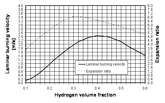 Figure 1: Laminar burning velocity and expansion ratio of hydrogen-air mixtures at NPT. 6) Determine the vent area by solving numerically the following transcendental equation (by changing area A until the right hand side of the equation is equal to the left hand side):
\frac{\displaystyle \mathrm{Br}_t \sqrt[3]{36\pi_\mathrm{0}} V^{2/3}}{\displaystyle {c_\mathrm{u}}_{\mathrm{i}}\sqrt{E_{\mathrm{i}/\gamma_\mathrm{u}}}} = \frac{A\displaystyle \left(1+\pi_{\mathrm{\displaystyle}}\right)^{0.4} \left[1 + 0.5\left(\frac{A}{V^{2/3}} \frac{{c_\mathrm{u}}_{\mathrm{i}}}{{S_u}_{\mathrm{i}}(E_{\mathrm{i}} - 1)}\right)^{0.8}\right]^{0.4}}{\displaystyle \alpha \left(1 + 2 V^{0.94}\right)^{0.4}{S_u}_{\mathrm{i}}\left(E_\mathrm{i}-1\right)} where
The correlations have been calibrated up to date against experimental data for hydrogen-air deflagrations for the following range of conditions: L/D \le 4.2;
V \le 37.4 m3;
0.005 \le A/V^{2/3} \le 0.34;
0 \ \text{kPa} \le p_{\mathrm{stat}} \le 13.5 \ \text{kPa};
p_{\mathrm{i}} = \text{1 bar abs.};
0.22 \le \pi_{\mathrm{red}} \le 5.
Bibliography
<< | Content | >> |
||||||||||||||||||||||||||||||||||||||||||||||||||||||||||||||||||||||||||||||||||||||||||||||||||||||||||||||||||||||||||||||||||||||||||||||||||||||||||||||||||||||||||||||||||||||||||||||||||||||||||||||||||||||||||||||||||||||||||||||||||||||||||||||||||||||||||||||